5 electrical interfaces, 1 rj-48 t1 * as a dce interface, Figure 17. rj-48 cable pin out -6 – CANOGA PERKINS 2461 E1 Modem User Manual
Page 24
EdgeAccess Universal Chassis System
4. Connect the -48 Volt source DC power leads to the terminal block. In so doing, you must
strictly observe the following order of connection to the source power supply wire:
(a) + terminal to red lead (GND)
(b) – terminal to black lead (-48VDC)
5. Tighten the two captive wire installation screws on the terminal block.
6. Plug the terminal block into the rear of the unit. Verify that the source wires are routed
downward.
7. Apply power and verify proper LED status of modem in power up condition (see Chapter 3).
2.5 Electrical Interfaces
The electrical interfaces on the 2461:
RJ-48 T1 (DCE) Interface Port
DA15 9-pin Command Port Interface on the standalone models
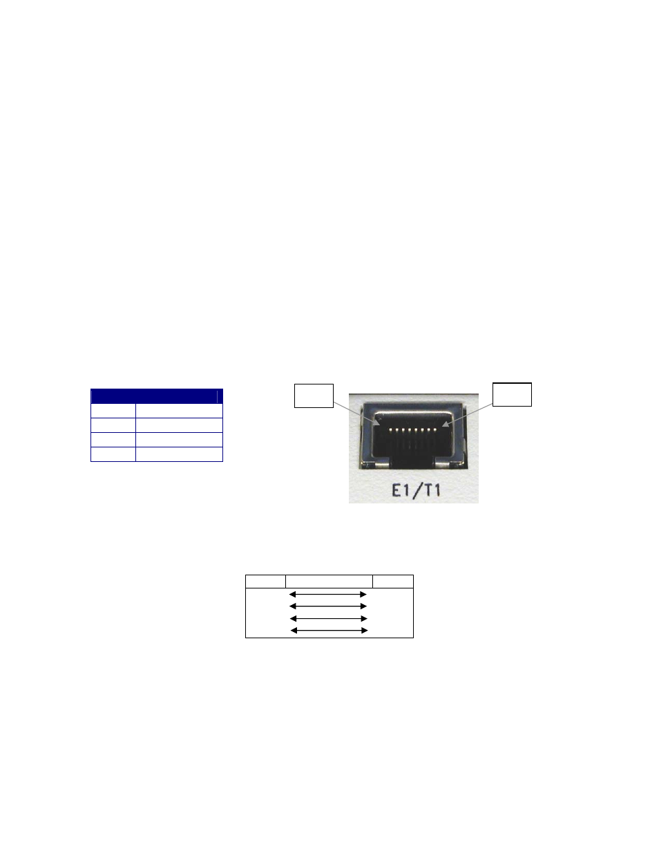
2.5.1 RJ-48 T1 * as a DCE Interface
Pin 8
Pin 1
PIN
Direction
1 Tx
(Output)
2 Tx
(Output)
4 Rx
(Input)
5 Rx
(Input)
Figure 17. RJ-48 Cable Pin Out.
RJ-48 connector X-Over cable * for a DTE Interface:
PIN
PIN
1 - Tx
4 - Rx
2 - Tx
5 - Rx
4 - Rx
1 - Tx
5 - Rx
2 - Tx
* Note: Any -RJ-48 Interface that is not labeled DCE is wired to accommodate DTE signals.
2461 Modem User Manual
2-6