4 providing power to the 2461-1400 modem, 4 providing power to the 2461-1400 modem -5, Figure 16. dc power entry close up -5 – CANOGA PERKINS 2461 E1 Modem User Manual
Page 23
EdgeAccess Universal Chassis System
Operation:
Note: When connecting the alarm output to an external source, use twisted pairs and terminate
the cable shield at the user side.
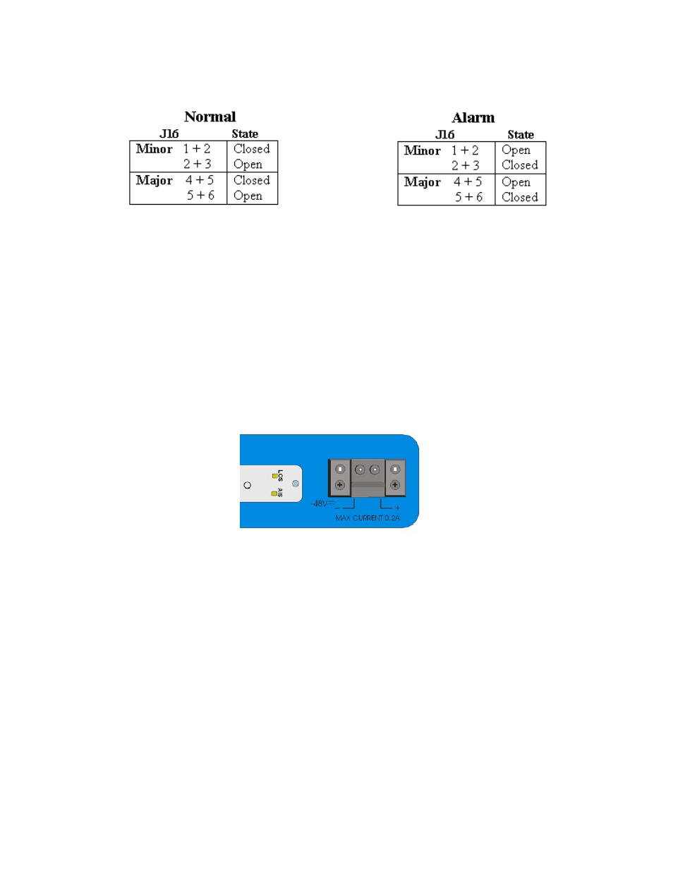
2.4 Providing Power to the 2461-1400 Modem
The -48 volt base unit is intended for use with an external -48VDC power source. A two piece
terminal block connector is provided. It is clearly marked as to which screw lug is to be attached
to the positive (+) and negative (-) 48 volts DC terminals.
Note: Check signal ground (Gnd) of the source supply and orient it to the Modem Gnd, or chassis
ground. Verify with a ohmmeter that (+) and (-) are not shorted prior to applying power.
Figure 16. DC Power Entry close up
Warning! Disconnect the -48VDC power source and use a voltmeter to measure the
voltage across the negative (-) and positive (+) source DC leads. Set the voltmeter to a
range that makes it capable of measuring up to 75VDC. The measurement across the
positive and negative leads should be zero (0) volts.
To provide power to the 2461 stand alone modem DC version, do the following:
1. Remove the power terminal block from the rear panel of the unit.
2. Using a 1/16-inch flat-blade (pocket) insulated screwdriver, loosen the two captive wire
installation screws on the terminal block to accommodate 16-22 AWG solid wire.
3. If you are establishing a color convention for wiring, use black for -48VDC and red for Gnd.
Remove ¼-inch insulation from wire ends. Avoid nicking the wire.
2461 Modem User Manual
2-5