Theory of operation, Radar beam illumination with 10 inch antenna, Radar beam illumination with 12 inch antenna – BendixKing IN-182A System RDR-2000 User Manual
Page 16
12
Effective Date: 5/98
RDR 2000 Pilot's Guide: Rev 3
Theory of Operation
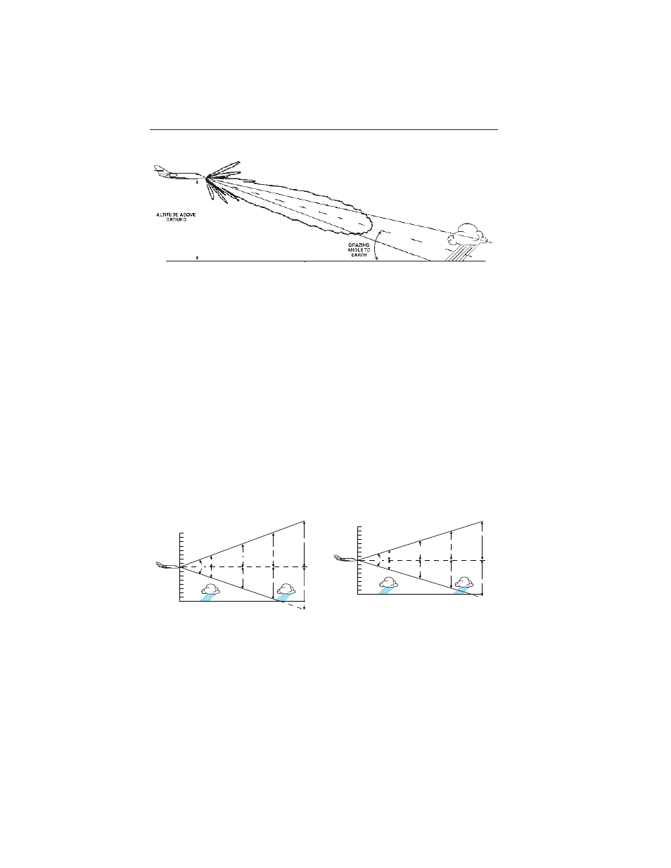
This tool should be understood and kept handy when trying to interpret
the weather display.This tool illustrates that at greater distances, the
weather cell doesn’t fill the cone shaped beam. Under these conditions
the distinction of the weather cell from the ground clutter is most difficult.
The following figure illustrates this condition.
In this scenario the weather cell might be at 100 nm, the altitude might
be 40,000 feet, and the appropriate tilt angle is approximately -3
degrees. Notice that the beam is centered on the rain but it also inter-
sects the ground. The angle the beam makes with the ground is called
the grazing angle. When this angle gets greater than about 2 degrees
the ground reflections that return to the radar become very significant. A
later section called “Tilt Management” discusses this difficult topic and
makes some suggestions to help make weather/ground distinction.
The following diagrams show the beam width relationship with 10 inch,
and 12 inch antennas. For illustrative purposes the aircraft are shown at
approximately 40,000 feet and the tilt is set at zero degrees.
0
Center of Radar Beam with Zero Tilt
26,600 FT
75
50
25
53,200 FT
39,900 FT
RANGE (NM)
100
13,300 FT
10
°
26,600 FT
53,200 FT
39,900 FT
13,300 FT
Radar Beam Illumination
with 10 Inch Antenna
0
Center of Radar Beam with Zero Tilt
21,250 FT
75
50
25
42,500 FT
31,900 FT
RANGE (NM)
100
10,600 FT
8
°
10,600 FT
21,250 FT
42,500 FT
31,900 FT
Radar Beam Illumination
with 12 Inch Antenna