3 the klr 10 display segments, The klr 10 display segments: -4, Table 2-2: klr 10 indicator segments -4 – BendixKing KLR 10 User Manual
Page 12
KLR 10 Pilot’s Guide
KLR 10 Controls
P/N D201306000109
Page 2-4
Rev 1 Feb 2014
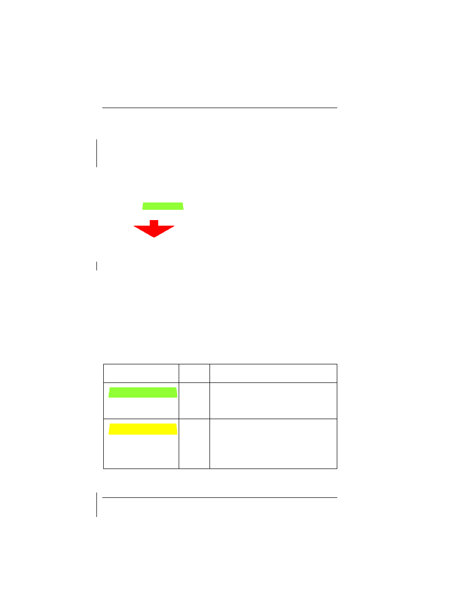
2.3 THE KLR 10 DISPLAY SEGMENTS:
The KLR 10 display has chevron and bar styled LED-driven color-
coded segments which, once correctly calibrated in accordance with
the BendixKing KLR 10 Installation Manual, part number
D201305000058, illuminate corresponding to the AOA of the aircraft.
The display will respond to the linear changes of the aircraft’s AOA
from Cruise, up to Stall and gives a repeatable, instantaneously
changing segment representation of that range. The display will
illuminate a series of transitional segments from no segments to the
Green Bar
(“Cruise” indication for the aircraft located at
the bottom of the display),
and on through to the
flashing Red
Arrow “
”
(stall indication for the aircraft located at the
top of the display).
A correctly calibrated KLR 10 will provide a linear increase in AOA
indication as the aircraft slows. The final “Too slow Too slow” alert
with flashing red arrow MUST be active prior to the actual
aerodynamic stall. Ensure during post-calibration testing that the
final KLR 10 alert state is displayed prior to any stall indications.
The 10 possible segment combinations are listed below. Every
aircraft will correlate the lit segment or combination of segments to
the specific aircraft’s AOA dynamics, once calibrated. The
relationship of when and which combination shows is unique to the
aircraft’s AOA and can be accurately correlated
ONLY when in-flight.
Table 2-2: KLR 10 Indicator Segments
SEGMENT
ABBR
CONDITION
G
Green Bar with no other segments
indicates Cruise set point, (lots of
lift).
Y1
Single lower Yellow Bar with no
other segments indicates
slowing/moderate AOA.