BendixKing KLR 10 User Manual
Page 11
KLR 10 Lift Reserve Indicator Pilot’s Guide
P/N D201306000109
KLR 10 Controls
Rev 1 Feb 2014
Page 2-3
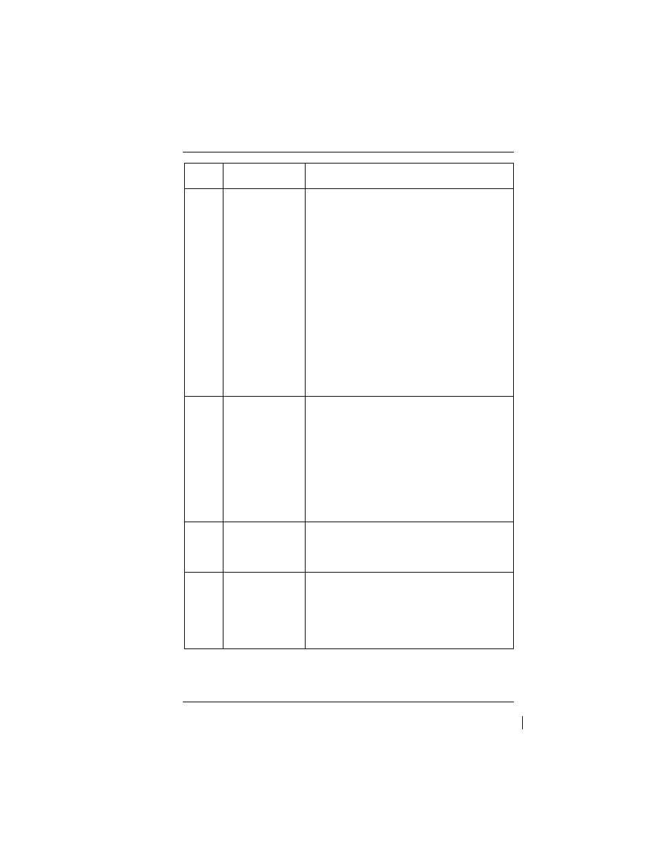
ITEM
CONTROL
FUNCTION
4
Brightness /
MODE Push
Button Switch
(Multiple
Functions)
The Brightness button is the black push
button on the lower right corner of the
display.
The Brightness button has 2 functions:
Changes the brightness levels of the
colored segments (Quickly push and
release to cycle thru 16 brightness
levels),
Operates as a
MODE switch, to enter
into and out of OAA and Cruise
calibration steps when the calibration
rotary switch is vertical. See page 2-7 for
more information on how to set the
Brightness levels.
5
The “CAL
SET” push
button
The calibration set push button is the
black button located at the bottom right
corner and is recessed underneath the
front case. The calibration set button is
used to enter selected calibration set
points (Ground Zero, OAA and Cruise)
during the calibration procedure. It can
be actuated using a pencil or other small
blunt pointer.
6
Display
Segments
Multicolored segments that correspond
to different angles of attack for the
aircraft.
7
Auto
Brightness
Photo Cell
The photo cell is in the top, middle of the
KLR 10 display and automatically
detects the ambient light changes which
will switch from
daytime brightness
preset to
nighttime brightness presets.