Wire the burner – Beckett CG10 User Manual
Page 12
12
Wire the Burner
Install the burner and all wiring in accordance with the
National Electric Code ANSI/NFPA 70 (Canada CSA
C22.1) and all applicable codes and requirements.
Wire the burner in compliance with all instructions and
diagrams provided by the appliance manufacturer.
Verify operation of all controls in accordance with the
appliance manufacturer’s guidelines.
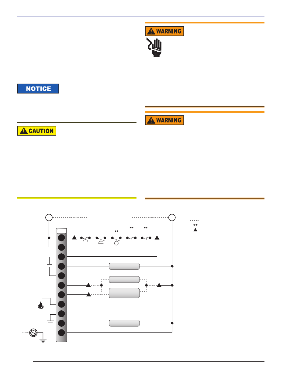
See Figure 9 for a typical wiring
diagram, with the RM7897A fl ame
safeguard control, for reference purposes only. Check
the literature that was packaged with the burner for the
primary control manufacturer’s instructions and the exact
wiring diagram for your specifi c burner.
Do Not Bypass Safety
Controls
Tampering with, or bypassing safety controls
could lead to equipment malfunction and result in
asphyxiation, explosion or fi re.
Safety controls are designed and installed to provide
protection.
Do NOT tamper with or bypass any safety control.
If a safety control is not functioning properly, shut
off all main electrical power and gas supply to
the burner and call a qualifi ed service agency
immediately.
y
y
y
Electrical Shock Hazard
Electrical shock can cause severe
personal injury or death.
Disconnect electrical power before installing or
servicing the burner.
Provide ground wiring to the burner, metal control
enclosures and accessories. (This may also be
required to aid proper control system operation.)
Perform all wiring in compliance with the National
Electrical Code ANSI/NFPA 70 (Canada CSA C22.1)
y
y
y
Keep Service Access
Covers Securely Installed
These covers must be securely in place to prevent
electrical shock, damage from external elements,
and protect against injury from moving parts.
All covers or service access plates must be in place
at all times except during maintenance and service.
This applies to all controls, panels, enclosures,
switches, and guards or any component with a cover
as part of its design.
y
y
Figure 9. Typical wiring using Model RM7897A (for reference only)
Section: Wire the Burner
Legend:
Key:
Wire Color:
Notes:
= Wired by Installer
= Provided by Installer
= Field Wiring Tie-in
Trans - Ignition Transformer
GV1 - On/Off Gas Valve
GV2 - High/Low Valve
LWCO - Low Water Cut-Off
A - White
B - Black
C - Blue
D - Orange
E - Brown/Red
G - Brown
K - Violet
L - Black/Red
For UV run white wire to G terminal and
blue wire to F terminal. For fl ame rod run
wire to F. G is a chassis ground.
* - clip and remove jumper JR1
Where a boiler management system
cannot supply motor power requirements
an isolation relay should be used.
1.
2.
3.
5
20
6
10
7
8
9
F
G
4
L2
JR1*
RM7897A
Trans
GV1
GV2
Motor
BK
BK
BL
OR
OR
L
C
K
D
E
A
A
A
A
B
B
B
G
G
C
A
Flame Rod
SEE NOTE 1
High Gas
Pressure
Low Gas
Pressure
LWCO
High
Limit
Operating
Control
L1
L2
Air
Proving
Swtich
LINE VOLTAGE SERVICE 120v 60Hz
FROM FUSED DISCONNECT
SUPPLIED BY INSTALLER
Equip
Ground (GND)
Terminal
GND