Prepare the burner – Beckett NX User Manual
Page 8
8
Combustion chamber — Burner retrofi tting
Verify that the appliance combustion chamber
provides at least the minimum dimensions given in
Table 3.
○
Chamber Dimensions (inches)
Firing Rate
(GPH)
Round
I.D.
Rectangular
Height Floor to
nozzle
Width
Length
0.50
8
7
8
12.0
5-6
0.75
9
8
9
12.0
5-6
1.00
10
9
10
12.5
5-6
1.25
11
10
11
12.5
5-6
1.50
12
11
12
13.0
6-7
1.75
14
12
15
13.5
6-7
Table 3. Chamber Dimensions
Prepare the Burner
General
In most cases, the burner is ready to mount to the
appliance. There can be situations where the burner
needs to be reconfi gured to perform properly in the
appliance. Review the appliance manufacturer’s
specifi cations prior to installing to determine if any
modifi cation is required to properly confi gure the burner.
Instruction on how to perform the following burner
preparation tasks can be found in the Professional
Maintenance section.
Remove / install burner nozzle
Check head / air adjusting plate
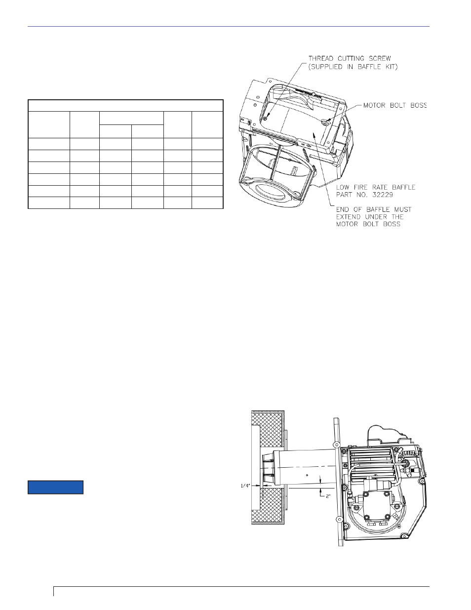
Low Firing Rate Baffl e (If specifi ed)
The NX Low Firing Rate Baffl e (LFRB), refer to Figure
3, reduces the burner airfl ow and pressure. Refer to the
appliance manufacturer’s instructions or the Beckett
OEM Specifi cation Guide part number 6711. To avoid
poor burner performance, do not omit the baffl e when
specifi ed or install the baffl e when not specifi ed.
○
○
Mount Burner on Appliance
Verify that the air tube installed on the burner provides
the correct insertion depth. Refer to Figure 4.
The end of the air tube should normally be 1/4” back
from the inside wall of the combustion chamber. Never
allow the leading edge of the retention ring to extend
into the chamber, unless otherwise specifi ed by the
appliance manufacturer.
Bolt the burner to the appliance using the fl ange that is
provided.
The Low Firing Rate Baffl e may
have been factory installed. If fi eld
installation is required, insert the Low Fire Rate Baffl e
into the housing, aligning the mounting screw hole with
the notched hole in the burner housing. Make note that
the curved end of the baffl e should be below the motor
bolt boss. Tighten the thread cutting screw to 12-24 in-lbs.
NOTICE
Figure 4. – Mounting Burner in Appliance
SK9668
Figure 3. – Mounting Low Fire Rate Baffl e in burner
housing.
SK9698
Section: Prepare the Burner