Beckett NX User Manual
Page 16
16
Section: Start the Burner and Set Combustion
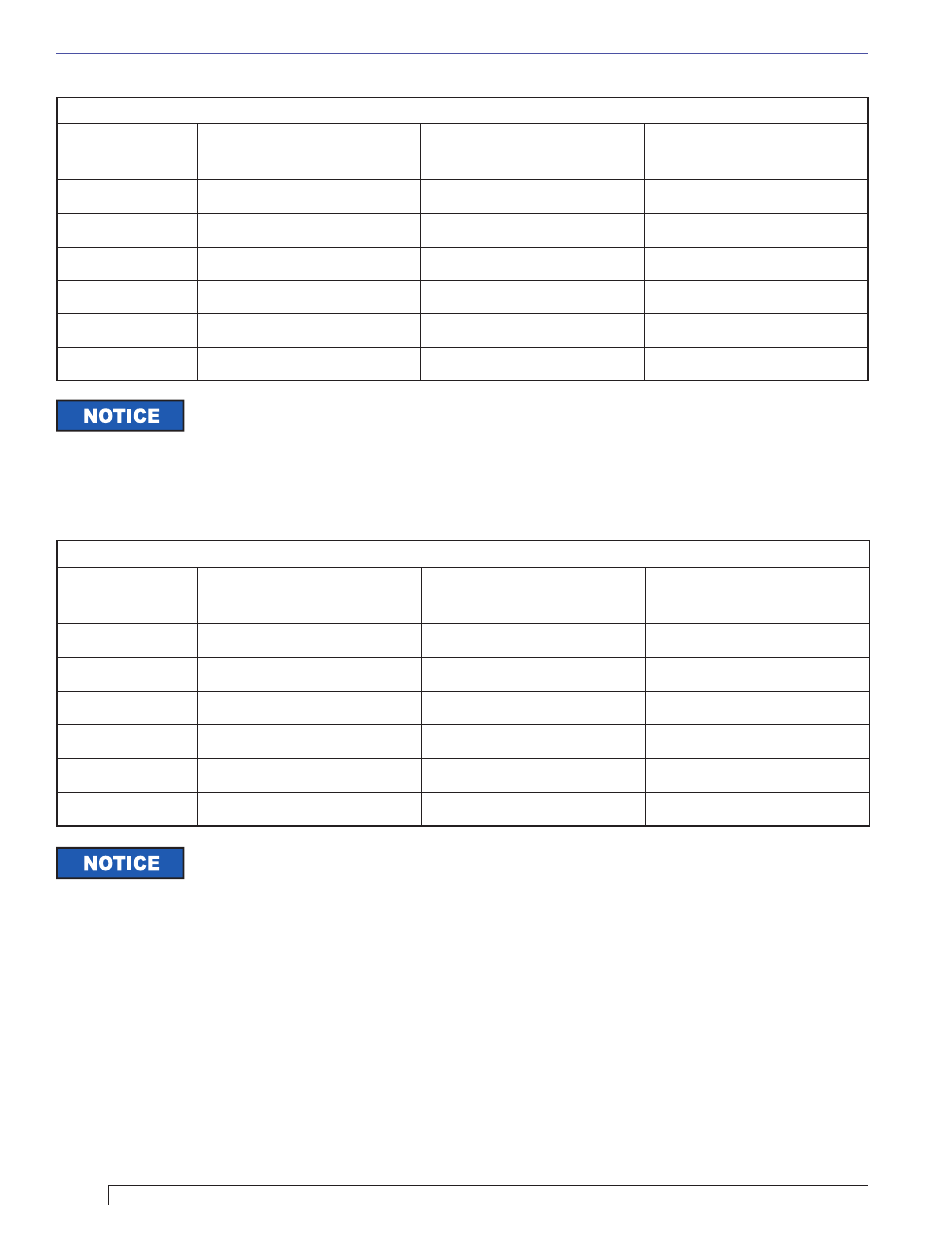
NX Air Tube & Head Combinations
Head/Air
Setting
LG - (9-slot head)
LH - (6-slot head)
LB - (9-slot head)
LC - (6-slot head)
LD - (9-slot head)
LF - (6-slot head)
0.5
0.40 – 0.50
--
1.10 – 1.25
1.0
0.45 – 0.60
--
1.20 – 1.35
2.0
0.55 – 0.70
0.85 – 1.05
1.30 – 1.45
3.0
0.65 – 0.80
0.95 – 1.15
1.40 – 1.55
4.0
0.75 – 0.90
1.05 – 1.25
1.50 – 1.65
5.0
0.85 – 1.00
1.15 – 1.35
1.60 – 1.75
The NX burner has a reduced diameter air tube, precision-designed air throttle cup and
combustion head for improved performance. This design provides very accurate control of the
air/fuel ratio, but the light reaching the cad cell through small holes in these components is limited. Because of this,
the average cad cell resistance may be higher than conventional burners with larger openings.
Table 7a. – NX Burners
NX Air Tube & Head Combinations
Head/Air
Setting
LG - (9-slot head)
LH - (6-slot head)
LB - (9-slot head)
LC - (6-slot head)
LD - (9-slot head)
LF - (6-slot head)
0.5
–
0.40 – 0.60
–
1.0
0.40 – 0.55
0.50 – 0.70
1.10 – 1.25
2.0
0.50 – 0.65
0.60 – 0.80
1.20 – 1.35
3.0
0.60 – 0.75
0.70 – 0.90
1.30 – 1.45
4.0
0.70 – 0.85
0.80 – 1.00
1.40 – 1.55
5.0
0.80 – 0.95
0.90 – 1.10
–
Use factory-set or manufacturer’s recommended Head/Air Setting for ‘Starting the Burner and
Setting Combustion’. The Head/Air Settings shown in Tables 7 are provided for reference
purposes and represent a general range of rates and settings. Individual appliances, vent systems, and fi eld
conditions will impact the overall burner set up required for satisfactory combustion performance.
Table 7b. – NX Burner with Low Fire Rate Baffl e (LFRB) Installed