Beckett NX User Manual
Page 20
20
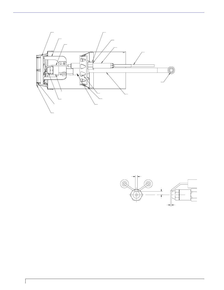
Figure 11. – Nozzle Line/Head/Air Tube Assembly (Low fi ring rate shown.)
Retention Head
Retention Head
Head Support Legs
Head Support Legs
Electrode Tips
Electrode Tips
Electrode Clamp
Electrode Clamp
Electrode Bracket
Electrode Bracket
Electrode Insulator
Electrode Insulator
Electrode Extension Rods
Electrode Extension Rods
Nozzle Adapter
Nozzle Adapter
Nozzle
Nozzle
Stops in Retention Ring
Stops in Retention Ring
Retention Ring
Retention Ring
Throttle Ring
Throttle Ring
Throttle Cup
Throttle Cup
Nozzle Line
Nozzle Line
Bulkhead Fitting
Bulkhead Fitting
SK9666A
SK9666A
Throttle Cup Hub
Throttle Cup Hub
Use a 5/8” open-end wrench to carefully remove the
existing nozzle.
Inspect the nozzle adapter before installing the
new nozzle. If it is grooved or scratched on the
sealing surface, replace the nozzle line assembly.
If the surface is damaged, oil could leak at the
nozzle to adapter joint, causing serious combustion
problems.
Protect the nozzle orifi ce and strainer when
installing. If the orifi ce gets dirt in it or is scratched,
the nozzle will not function properly.
To install a new nozzle, place a 3/4” open-end
wrench on the nozzle adapter. Insert the nozzle
into the adapter and secure fi nger tight. Finish
tightening with a 5/8” open-end wrench. Use care
to avoid bending the burner head support legs or
electrodes.
Do not over-torque the nozzle when installing. This
will cause deep grooves in the nozzle adapter,
preventing a seal when a new nozzle is installed.
Carefully check and realign the electrode tips after
replacing a nozzle, ensuring the electrode settings
comply with Figure 12.
If the head was removed when replacing the
nozzle, carefully reconnect the head to the nozzle
adapter. Make sure to align the key in the support
leg with the keyway in the nozzle adapter and
to butt the head support to the nozzle adapter
shoulder, see Figure 13.
4.
5.
6.
7.
8.
9.
10.
Check/Adjust Electrodes
Check the electrode tip settings, as shown in Figure
12. If necessary, adjust by loosening the electrode
clamp screw (Figure 11) and slide/rotate the
electrodes as necessary. When the adjustment is
complete, securely tighten the clamp screw.
Note that if the throttle cup is moved be sure to
reposition it with no gap between the nozzle adapter
and hub.
○
○
Section: Perform Regular Maintenance
Check Retention Head Alignment and Cad
Cell Sighting
(Refer to Figure 13.)
The cad cell sighting holes in the throttle cup and
the retention head must be aligned to allow the cad
cell to detect the fl ame. Make sure the stamped key
in the retention head collar lines up with the keyway
in the nozzle adapter when mounting the retention
head. Note that in specifi c applications, the retention
head may not have a sighting hole.
○
Figure 12 - Electrode tip gap and spacing
5/32 GAP
1/4 above
nozzle center
1/8 Nozzle-to-tip
Spacing
5/32” Gap
1/4” Above
nozzle center
3/32” Nozzle-to-tip
spacing