Start the burner and set combustion – Beckett NX User Manual
Page 15
15
NX Burner Manual
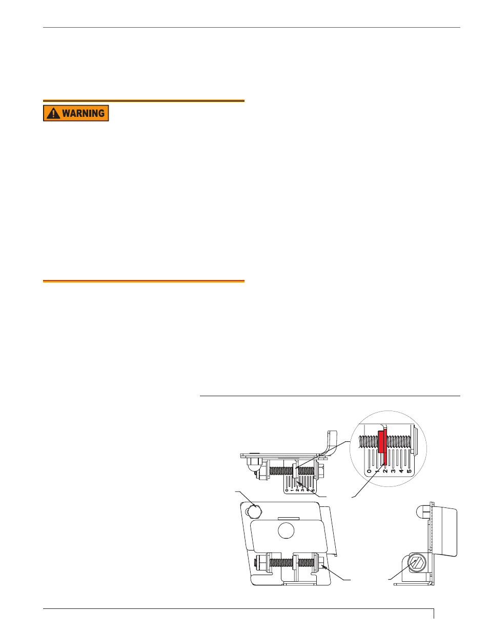
Pointer
Zero Setting
Locking Nut
Adjustment
Screw
Am52000
Section: Start the Burner and Set Combustion
Start the Burner and Set
Combustion
Start-up and Initial Settings
in the fl ue pipe between the appliance and the
barometric draft regulator. Seal this hole when
testing is complete. (See appliance manufacturer’s
instructions for location.)
Check/Adjust Zero Calibration Head/Air
Adjustment Mechanism. Refer to Figure 10.
The rear service door must remain closed for
this proceedure.
Loosen the splined nut approximately one turn.
A 5/16” nut driver or fl at blade screwdriver can
be used to turn the adjustment screw for head/
air setting.
Slightly loosen the zero setting acorn nut.
Turn the screw until the reading is set to zero.
(Mid-point of pointer should line up with zero.
Turn the air adjustment screw counterclockwise
to adjust the plate with the pointer to the zero
position.
Slide the nozzle line assembly forward until the
retention head engages the fi xed stops in the
retention ring at the end of the air tube.
Tighten the zero setting acorn nut.
The adjustment screw may now be turned
clockwise to adjust the head/air setting.
Turn the adjusting screw to a setting 1/2 number
lower than the proper setpoint as indicated
in Tables 7a and 7b. Then turn the adjusting
screw counterclockwise to the proper setting.
Tighten the splined nut after the head/air setting
has been adjusted.
7.
a.
b.
c.
d.
e.
f.
g.
h.
i.
j.
k.
Do not allow oil to spray into a hot combustion
chamber while bleeding air from the pump.
Install a gauge in the nozzle discharge port tubing
or fully open the pump bleed valve to prevent oil
spray from accumulating in the combustion chamber
during the air bleed procedure.
Ensure that all bubbles and froth are purged from
the oil supply system before tightening the pump
bleed valve.
Ensure that the appliance is free of oil and oil vapor
before starting or resetting the burner.
y
y
y
y
Failure to prime the pump properly could result in
unstable combustion, hot gas puff-back and heavy
smoke.
Hot Gas Puff-Back and
Heavy Smoke Hazard
Figure 10. – Head/air Adjustment Plate Assy.
Open the shutoff valves in the oil supply line to the
burner.
Referencing Figure 10, verify and/or set the
Head/Air Adjustment Pointer to the value specifi ed
by the Appliance Manufacturer. If the Appliance
Manufacturer’s values are not available, refer to
Table 7a or 7b. (This is an initial air setting for
the pump bleeding procedure only.) Calibrated
test instruments must be used for the fi nal head/air
adjustment.
Adjust the thermostat or
temperature controller to call for
heat. (Note: return controller(s)
to the original settings upon
completion of burner installation
or service.)
Close the line voltage switch to
start the burner. If the burner
does not start within the 3 to 10
second safety start check timing,
you may have to reset the safety
switch on the burner primary
control.
Bleed the air from the fuel pump
as soon as the burner motor
begins rotating.
Prepare for combustion tests
by drilling a 1/4” sampling hole
1.
2.
3.
4.
5.
6.