Manual-4, Operating instructions, Block diagram – Rane SM 82 User Manual
Page 6
Manual-4
LEFT
(MONO)
INPUT
CHANNEL 1
+6 dB
BALANCE
INPUT
RIGHT
LEFT
(MONO)
INPUT
RIGHT
RFI
FILTER
FILTER
RFI
INPUT
LEVEL
+6 dB
INPUT
OVERLOAD
OL
SENSE
CH 2
LEVEL
SEND
RIGHT MAIN
RIGHT SEND
LEFT MAIN
LEFT SEND
R
R
L
L
L
L
R
R
CH 3
L
L
R
R
CH 4
L
L
R
R
CH 5
L
L
R
R
CH 6
L
L
R
R
CH 7
L
L
R
R
CH 8
0 dB
0 dB
SUMMING
AMPLIFIERS
DRIVERS
BALANCED
BALANCED
DRIVERS
OUTPUT
BALANCE
AMPLIFIERS
SUMMING
0 dB
0 dB
+
L+R
LOOP
SENDS
RIGHT
LEFT
OUT
EXPAND
MAIN
RING
TIP
RIGHT
LEFT
+6 dB
+6 dB
LEVEL
OUTPUT
SENSE
OL
OVERLOAD
OUTPUT
LEFT
RIGHT
MAIN
OUTPUTS
SENSE
OL
OVERLOAD
RECEIVE
+6 dB
LEVEL
RECEIVE
RFI
FILTER
FILTER
RFI
RIGHT
INPUT
RECEIVE
BALANCE
+6 dB
RETURNS
INPUT
(MONO)
LEFT
LOOP
LEFT
RIGHT
TIP
RING
MAIN
EXPAND
INPUT
INPUT
EXPAND
LOOP
RING
TIP
RIGHT
LEFT
OPERATING INSTRUCTIONS
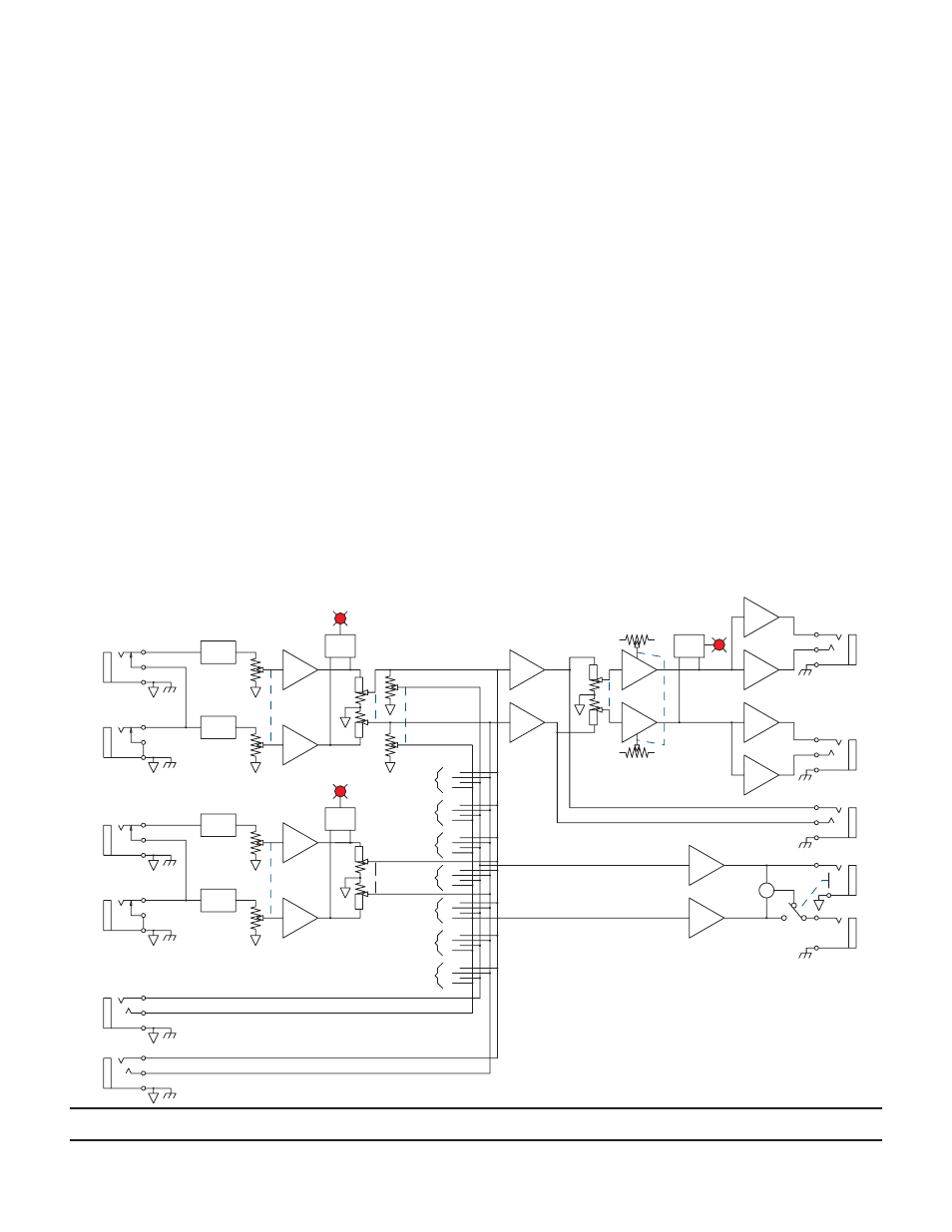
CIRCUIT DESCRIPTION
Learning to operate the SM 82 might be a bit easier if you
glance at the Block Diagram below. All eight stereo Inputs
operate in exactly the same way. Signal applied to the Inputs is
acted on by a radio interference filter (we have assumed that local
broadcasts should not be a part of your music) and is then routed
to a stereo LEVEL control. If you are using a mono source, con-
nect it only to the LEFT Input to send this mono signal to both
the Left and Right sides of the input circuitry. The output of the
Level control sections is applied to a unity gain buffer to prevent
the LEVEL control from adversely interacting with downstream
circuitry. The Input overload sensor monitors here to alert the
user via LED to any possible Input overload conditions. Left and
Right audio is then subjected to the channel BALance control to
allow the user to place the stereo image of the source as desired
to the Left and Right Outputs. If a mono input is present, the
BALance control becomes a PAN control. After the BALance
control has done its job, a stereo SEND LEVEL control adjusts
the amount of each Input routed to the Loop Output.
All eight stereo Inputs are simultaneously adjusted for stereo
placement by the OUTPUT BALance control. The resultant sig-
nal is added together and fed to the OUTPUT LEVEL control,
which has it’s own Overload indicator. The main Outputs are
fully actively balanced, allowing the use of correctly wired long
cables.
EFFECTS LOOP
The LOOP SENDS receive their audio from the Send bus
which is the sum of all the Inputs as determined by the Input
SEND controls. This Output may be used to drive a stereo
effects processor. The output of the effect device is returned to
the SM 82 through the LOOP RETURNS. The level of the
returned effect is determined by the RETURN LEVEL control
on the front panel. The return section also provides a BALance
control for image placement.
BALANCE CONTROLS
These do not increase the level of either Left or Right signal.
As the controls are moved toward one channel, the level of the
other channel is only reduced.
HIGH NOISE IMMUNITY
One of the most unusual features of the SM 82 is its inher-
ent immunity from noise. All eight of the stereo inputs may be
turned all the way up without increasing the internal noise of the
mixer. This is critical due to the wide variation in output levels
found in musical instruments and tape devices. A fairly low-level
synthesizer may be combined in the same system with a high
level unit without any undesirable side-effects. The SM 82 elimi-
nates the concerns normally associated with mixing so-called -l0
dBV units with +4 dBu types.
©Rane Corporation 10802 47th Ave. W., Mukilteo WA 98275-5098 USA TEL 425-355-6000 FAX 425-347-7757 WEB www.rane.com
107271
Block Diagram