Manual-3 rear panel description – Rane SM 82 User Manual
Page 5
Manual-3
REAR PANEL DESCRIPTION
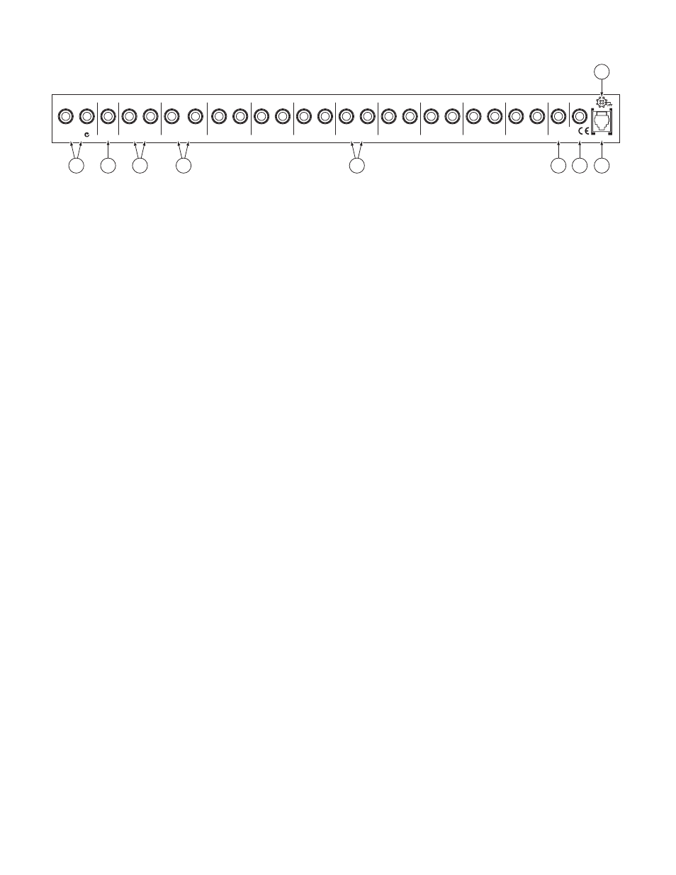
1
Main OUTPUT:
These balanced Tip-Ring-Sleeve jacks are used to connect the main Outputs of the SM 82 to a power amplifier
or to additional signal processing. As is the standard with all Rane balanced outputs using ¼" TRS jacks, the Tip is (+), the Ring
is (–) and the Sleeve is ground.
2
MAIN EXPAND OUTPUT:
This ¼" TRS stereo (Tip = left, Ring = right) Output jack connects one SM 82 to another for the
purpose of expanding the number of Inputs available in the system. Only a stereo plug and cord should be used. To do otherwise
will cause loss of Right channel signal and possibly distortion to the Left channel. This Output also serves as a fixed pre-fader level
useful as tape outputs or other applications.
3
LOOP RETURN:
These ¼" aux returns may connect the output of a reverb or other effect unit to the Loop bus of the
SM 82. If no effect is used, they can be used as a ninth stereo Input to the mixer in addition to those described in 5.
As with the other stereo Inputs, mono signal may be connected to the LEFT input to obtain two channel mono operation.
4
LOOP SEND:
This pair of ¼" jacks may drive an effect or similar device which is to be returned to item 3 above.
If a mono device is used, both the Left and Right Send channels of the SM 82 are summed together and presented at the LEFT
Output if nothing is inserted in the RIGHT Output.
5
Channel Input jacks:
consist of Eight pairs of unbalanced ¼" tip-sleeve jacks, used to connect any line-level signal source to the
SM 82. As indicated, only the LEFT is to be used if the Input is mono and should therefore appear in both Left and Right chan-
nels, depending on the position of the front panel BALANCE control which is now effectively a PAN.
6
MAIN EXPAND INPUT:
A ¼" TRS stereo Input jack may link two or more SM 82s together. The Left input is on the Tip,
Right on the Ring and the Sleeve is ground. This may also be used to sum any fixed-level stereo signal into the Main Outputs,
producing a tenth stereo Input when added with 5 and 3. As in 2 above, use only a stereo TRS cable.
7
LOOP EXPAND INPUT:
Another ¼" TRS stereo Input, expands the stereo Loop buses of two SM 82s similar to the MAIN
EXPAND OUTPUT in 2. A stereo Tip-Ring-Sleeve cable must be used for this application. Connect the LEFT and RIGHT
LOOP SENDS (4) of the first unit to the LOOP EXPAND IN of the second unit. (Tip = left; Ring = right.)
8
Remote POWER supply input:
Use only an RS 1 or other remote AC power supply approved by Rane. The SM 82 is supplied from
the factory with a remote power supply suitable for connection to this input jack. The power requirements of the SM 82 call for an
18-24 volt AC center-tapped transformer only. It is not a telephone jack. Using any other type of supply may damage the mixer and
will void the warranty (which at two years parts and labor is worth safeguarding).
9
Chassis ground point:
A #6-32 screw is provided for chassis grounding purposes. See the note below for details.
CHASSIS GROUNDING
If after hooking up your system it exhibits excessive hum or buzzing, there is an incompatibility in the grounding configuration
between units somewhere. Your mission is to discover how your particular system wants to be grounded. Here are some things to try:
1. Try combinations of lifting grounds on units that are supplied with ground lift switches or links.
2. If your equipment is in a rack, verify that all chassis are tied to a good earth ground, either through the line cord grounding pin or
the rack screws to another grounded chassis.
3. Units with outboard power supplies, such as the SM 82, do not ground the chassis through the line cord. Make sure that these
units are grounded either to -another chassis which is earth grounded, or directly to the grounding screw on an AC outlet cover by
means of a wire connected to a screw on the chassis with a star washer to guarantee proper contact.
Please refer to the RaneNote, “Sound System Interconnection” (supplied in this manual and available separately) for further infor-
mation on system grounding.
MADE IN U.S.A.
ALL INPUTS ARE UNBALANCED
RANE CORP.
RING=R
TIP=L
RING=R
TIP=L
POWER
300mA
SM 82
8
LEFT
RIGHT
LEFT
RIGHT
LEFT
RIGHT
LEFT
RIGHT
EXPAND
MAIN
(MONO)
OUTPUT
(MONO)
(MONO)
7
LEFT
RIGHT
(MONO)
6
LEFT
RIGHT
(MONO)
5
LEFT
RIGHT
(MONO)
4
LEFT
RIGHT
(MONO)
3
LEFT
RIGHT
(MONO)
2
LEFT
RIGHT
(MONO)
1
LEFT
RIGHT
(MONO)
LOOP RETURN
UNBALANCED
OUTPUT
BALANCED
LOOP SEND
UNBALANCED
MAIN
LOOP
EXPAND
EXPAND
INPUT
CLASS 2 EQUIPMENT
INPUT
ACN 001 345 482
1
3
4
5
2
6 7 8
9