Rane RA 27 User Manual
Page 3
Manual-2
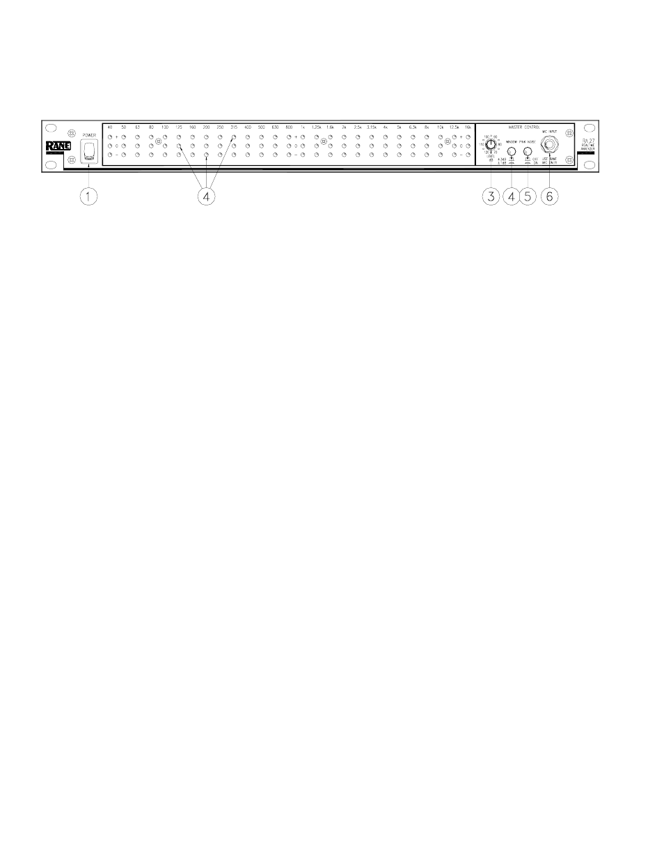
FRONT PANEL DESCRIPTION
ᕃ POWER switch: You’ve probably figured this one out by now...
ᕄ Analyzer display LEDs: Each red LED lights up when response is too high in that band; green LEDs light when response
is within ±3 dB or ±1 dB of the selected curve; yellow LEDs come on when response is too low.
ᕅ LEVEL control: Use this knob to adjust the microphone level (or line level when the microphone is unplugged) to properly
drive the display. This control is accurately calibrated in dB-SPL; any display band whose LED is green has the sound
pressure level indicated by this knob (only with the mic plugged in).
ᕆ WINDOW switch: In the ±3 dB position, the green LED in each band lights when signals of that frequency are within 3 dB
above or below the Normal or House curve, whichever is selected. In the ±l dB mode, system response must be within l dB
above or below the selected curve to light the green LEDs.
ᕇ PINK NOISE switch: Engage to activate the built-in pink noise generator. Be sure your system is turned down before
engaging this switch to prevent scaring yourself.
ᕈ MICROPHONE INPUT jack: PLUG ONLY THE RANE MICROPHONE INTO THIS JACK – THE DC VOLTAGE
SUPPLIED BY THIS JACK COULD BE DAMAGING TO ANY OTHER MICROPHONE. When the mic is plugged in, the
display responds to whatever the mic picks up; when the mic is unplugged, the MIC INPUT jack automatically switches the
display to monitor the LINE INPUT jack signal on the rear.