Manual- rear panel description – Rane PE 17 (2003 version) User Manual
Page 3
Manual-
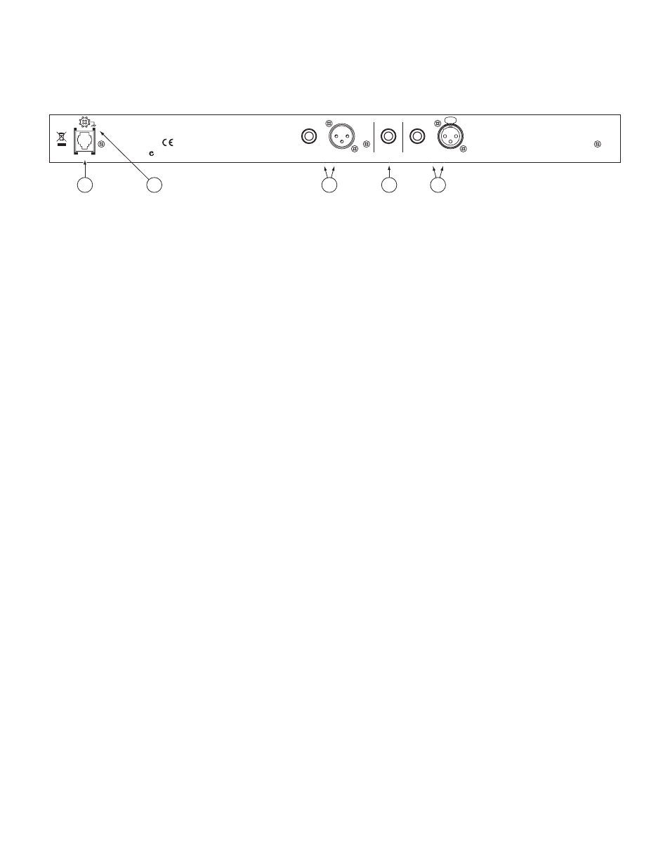
REAR PANEL DESCRIPTION
CHASSIS GROUNDING
After hooking up your system, if it exhibits excessive hum or buzzing, an incompatibility in the grounding configuration between
units exits. Ha! Now you earn your money, now you pay the piper. Now you must discover how your particular system wants to be
grounded! Here are some things to try:
Always use balanced interconnection methods—but, when you can’t:
1. Try combinations of lifting grounds on units supplied with ground-lift switches or jumpers.
2. If your equipment is in a rack, verify that all chassis are tied to a good earth ground, either through the line cord grounding pin or
the rack screws to another grounded chassis.
Units with outboard power supplies like the PE 17, do nOt ground the chassis through the line cord. Make sure this unit is grounded
either to another chassis which is earth grounded (like the power amplifier), or directly to the grounding screw on an AC outlet cover
by means of a wire connected to the chassis ground point found on the rear to guarantee proper contact.
See the included RaneNote “Sound System Interconnection” for more troubleshooting and specific cable matching.
1
XLR & ¼" TRS INPUT jacks:
Choose between one of these inputs. The ¼" TRS Input is a differentially active balanced, auto
unbalanced ¼" INPUT connector; tip = positive, ring = negative, and sleeve = signal ground. For unbalanced operation, use only a
standard mono (single conductor )tip-sleeve (no ring) plug. The balanced XLR INPUT connector is wired: pin 1 chassis ground, pin
2 positive, and pin 3 negative. These Inputs parallel each other and may be used for daisy chaining purposes, but do not use to sum
two Inputs together.
2
XLR & ¼" OUTPUT jacks:
These jacks are active balanced Ouputs. The ¼" TRS tip is signal positive, the ring is signal negative
and the sleeve is signal ground. The 3-pin wiring is per IEC/ANSI/AES standards: pin 1 signal ground, pin 2 positive, and pin 3
negative. These jacks parallel each other and unlike the Input, may deliver two Ouputs simultaneously.
3
PATCH I/O connector:
This ¼" TRS jack provides an unbalanced I (Input) on its tip and an unbalanced O (Output) on its
ring. This is designed for use with tip=send/ring=return effect loops found on many mixing consoles, providing an easy means for
patching the unit into effect loops using only a single ¼" TRS (2-conductor) patch cable. Caution: Use either the PAtCH I/O or
the InPUt and OUtPUt connectors — do not use both. These are not summing Inputs.
4
Remote POWER supply input:
This unit is supplied from the factory with a model RS 1 Remote AC Power Supply suitable for
connection to this jack. This unit requires an 18 volt AC center-tapped transformer only. This is not a telephone jack. never use a
power supply other than the one supplied or a Rane approved replacement.
5
Chassis ground point:
A #6-32 screw used for chassis grounding purposes. See the note below.
MADE IN U.S.A.
RANE CORP.
USE ONLY ONE
MAY USE BOTH
PE 17
INPUTS
PATCH I/O
TRS
TRS
OUTPUTS
CLASS 2 EQUIPMENT
ACN 001 345 482
POWER
450mA
PATCH I/O
MAY CONNECT TO THE INSERT
LOOP OF OTHER EQUIPMENT
USING A 1/4" TRS CABLE.
CAUTION! DO NOT USE THE
PATCH I/O WITH ANOTHER
INPUT! SEE THE MANUAL!
WIRING
TIP / PIN 2 = POSITIVE
RING / PIN 3 = NEGATIVE
SLEEVE = SIGNAL GROUND
PIN 1 = CHASSIS GROUND
WIRING
TIP = INPUT
RING = OUTPUT
SLEEVE = CHASSIS GROUND
4
5
3
2
1