Manual- front panel description – Rane PE 17 (2003 version) User Manual
Page 2
Manual-
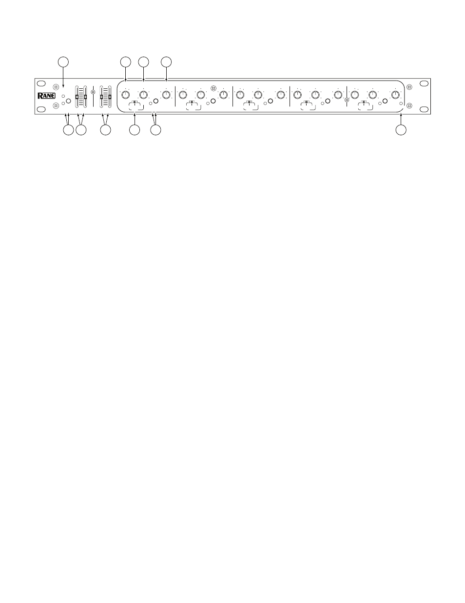
FRONT PANEL DESCRIPTION
1
Overall OverLoad indicator:
illuminates whenever the signal level at any of five critical nodes comes within 3 dB of clipping.
2
Overall BYPASS switch & indicator:
Engaging this pushbutton energizes the Bypass relay. This provides a complete hard-wire
Bypass of the PE 17 with no active electronics in the signal path. A red LED indicates the unit is in the BYPASS mode. In the out
(LED off ) position, the Input is routed through the active electronics. The Bypass relay is wired such that upon power failure it
reverts to the BYPASS condition, thus providing a “fail-safe” feature.
3
IN & OUT GAIN controls:
set the relative IN and OUT gain structures. The range of each is ±12 dB; however, note that the
labeling is opposite to each other, e.g., the top of the IN control reads +12 dB while the top of the OUT control reads -12 dB.
Configured this way, whenever they are held and moved together the overall gain through the PE 17 stays at unity. Positioning
these controls (together) as far toward the top of the panel as possible (without lighting the OL indicator) yields the best signal-to-noise
performance.
4
LOW & HIGH CUT FILTER controls:
set the corner frequencies of the band limiting filters. The frequencies shown represent
the -3 dB points for each filter. When the sliders are located at their bottom-most positions, the filters are at their lowest and high-
est extremes and thus, effectively bypassed.
5
FILTER LEVEL control:
The center detent position guarantees flat response through the respective filter due to its grounded
center-tap design. Full clockwise rotation yields 12 dB of boost, while full counterclockwise rotation gives you 15 dB of cut.
6
FREQUENCY multiplier switch:
The markings on this three position slide switch indicate the factor by which the calibrations
of the Frequency sweep control (7) are multiplied. For instance, if the range switch is in the “x0.1” position and the FREQUEN-
CY control is at “460,” then the actual center frequency of the filter is 46 Hz. Operation of this switch in conjunction with the
FREQUENCY control yields a range of 10 Hz to 20 kHz for each band.
7
FREQUENCY sweep control:
increases the center frequency of the filter band as it is turned clockwise. It is calibrated from
“100” to “2k.” The exact frequency is determined by multiplying the value indicated by the frequency multiplier switch (6).
8
Individual band BYPASS switch & indicator:
Each of the five filter BYPASS switches disables the respective filter, providing in-
stant comparison between flat response and equalized response. The red LED illuminates when the band is in the BYPASS mode.
9
BANDWIDTH control (Q):
Full counterclockwise rotation yields a Bandwidth of 1/30-octave (Q=43) in the respective filter,
while full clockwise rotation gives a 2 octaves (Q=0.67) bandwidth.
0
POWER indicator:
When this yellow LED is lit, the unit is powered and ready to command.
OCTAVE
dB
Hz
-15
12
-6
9
6
.03
100
2k
150
1k
0.3
2.0
1.8
-12
3
235 460
0.6
1.0
-3
OCTAVE
dB
Hz
-15
12
-6
9
6
.03
100
2k
150
1k
0.3
2.0
1.8
-12
3
235 460
0.6
1.0
-3
OCTAVE
dB
Hz
-15
12
-6
9
6
.03
100
2k
150
1k
0.3
2.0
1.8
-12
3
235 460
0.6
1.0
-3
OCTAVE
dB
Hz
-15
12
-6
9
6
.03
100
2k
150
1k
0.3
2.0
1.8
-12
3
235 460
0.6
1.0
-3
OCT.
dB
Hz
-15
12
-6
9
6
.03
100
2k
150
1k
0.3
2.0
1.8
3
235 460
0.6
1.0
-3
–12
0
0
–12
30k
40k
10k
5k
3k
20
10
35
80
180
250
EQUALIZER
PARAMETRIC
+12
+12
BYPASS
x1
x10
BYPASS
x0.1
OL
GAIN
1
POWER
CUT FILTERS
OUT
IN
LOW
HIGH
BANDWIDTH
LEVEL
FREQUENCY
x1
x10
x0.1
x1
x10
x0.1
x1
x10
x0.1
x1
x10
x0.1
BYPASS
2
BANDWIDTH
LEVEL
FREQUENCY
BYPASS
3
BANDWIDTH
LEVEL
FREQUENCY
BYPASS
4
BANDWIDTH
LEVEL
FREQUENCY
BYPASS
5
BANDWIDTH
LEVEL
FREQUENCY
PE 17
FREQ
FREQ
FREQ
FREQ
FREQ
1
5
7
8
2
6
10
9
3
4