Rane MX 23 User Manual
Page 3
Manual-2
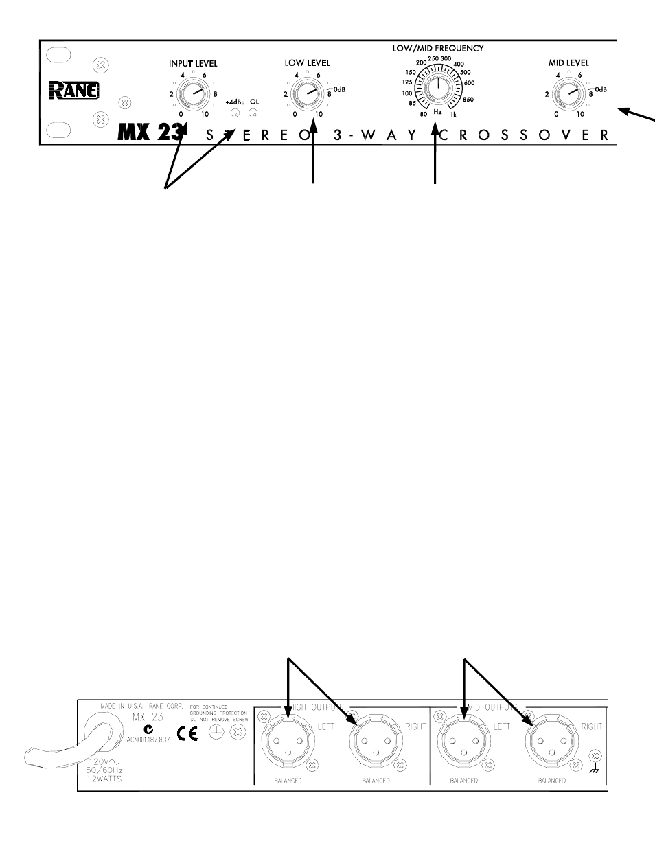
HIGH OUTPUTS
These are balanced Output jacks. Connect
the LEFT HIGH OUTPUT to the left channel
input of the high frequency amplifier, and
the RIGHT HIGH OUTPUT to the right
channel input of the high frequency
amplifier. When using different model
amplifiers for the low and high outputs, use
the amplifier with the most wattage for the
low outputs.
INPUT LEVEL control and
indicators
This controls the overall level without
altering the relative settings of the Low, Mid
and High frequency Outputs. Input gain is
+6 dB at “10”. With signal applied, set this
control so the +4 dBu LED lights occasion-
ally, indicating sufficient signal. Flashing of
the OL (overload) LED during peaks can be
avoided by turning the INPUT LEVEL down.
LOW LEVEL control
This controls the level of signal going to the
LOW OUTPUT jacks. Unity gain is reached at
the “0 dB” mark with the INPUT LEVEL set
to “10”. This control does not affect the
MONO SUB OUTPUT level. Refer to Operating
Instructions on page Manual-6.
LOW/MID FREQUENCY control
This 31-position selector sets the crossover
frequency between the Low and MId
frequency Outputs in both Channels. Consult
the manufacturer of the drivers or cabinets
for the correct setting.
MID OUTPUTS
These are balanced Output jacks. Connect
the LEFT MID OUTPUT to the left channel
input of the mid frequency amplifier, and the
RIGHT MID OUTPUT to the right channel
input of the mid frequency amplifier.
Cable Wiring
In agreement with IEC and AES/ANSI
standards, Rane wiring convention is pin 2
Positive (hot), pin 3 Negative (cold or
return), and pin 1 signal grounded and
chassis grounded (to allow unbalanced
operation). The XLR case is chassis
grounded.
This device uses low impedance
balanced line drivers. Do not connect the
“+” or “–” output pins to ground, as this
may cause the power supply to shut down.
For unbalanced use, leave the unused output
pin (“+” or “–”) unterminated.