Rane MP 24 User Manual
Page 4
Manual-4
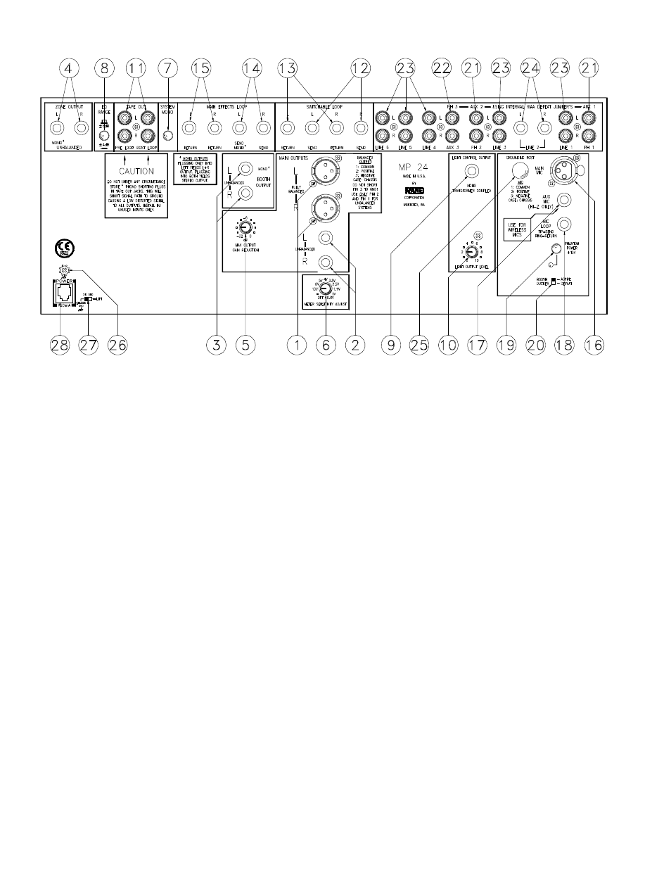
REAR PANEL DESCRIPTION
1. BALANCED MAIN OUTPUT connectors: These three-pin connectors provide a fully balanced Main Output signal, pin 2
is (+), pin 3 is (–) and pin 1 is signal ground. Pin 3 must never be grounded for unbalanced operation. Use only pin 2 as hot
and pin 1 as return for any unbalanced operation.
2. UNBALANCED MAIN OUTPUT connectors: These ¼" unbalanced connectors provide MAIN OUTPUT signals.
3. BOOTH OUTPUT connectors: Connecting to the Left Output only supplies a mono BOOTH monitor OUTPUT; connect-
ing to both Left and Right provides a stereo Output.
4. ZONE OUTPUT connectors: Connecting to the Left Output only supplies a mono ZONE OUTPUT, connecting to both
Left and Right provides a stereo Output. The Zone Outputs are located Post-EQ, which includes the Microphone Output.
An internal jumper block programs the Zone to Pre-EQ (and no mic) if required. See SERVICE INFORMATION on page
Schematic-1.
5. MAXIMUM OUTPUT GAIN REDUCTION control: This rotary control decreases the maximum Level of the balanced
and unbalanced MAIN OUTPUTS of the MP 24 as it is rotated CCW.
6. METER SENSITIVITY ADJUST: Clockwise rotation decreases the full-scale sensitivity of the PEAK PROGRAM
METER, as indicated by the full-scale voltage calibrations around the control.
7. SYSTEM MONO/STEREO switch: Engaging this pushbutton converts all Outputs (except tapes and loops) to MONO,
regardless of the nature of the Input signals.
8. EQ RANGE switch: In the out position, the maximum boost/cut available from the Program Equalizer is ±8dB. In the
switch’s in position, this range is reduced to ±4 dB.
9. LIGHT CONTROL OUTPUT jack: This ¼" TRS connector provides a transformer-coupled mono program signal for use
by a lighting controller’s trigger input. The tip is positive, the ring is negative and the sleeve is floating.
10. LIGHT OUTPUT LEVEL attenuator: Counter-clockwise rotation reduces the Output Level at the LIGHT CONTROL
OUTPUT jack.
11. TAPE OUTPUT jacks: One pair of RCA jacks provides pre-EQ, pre-LOOP Program Outputs. The other pair supplies pre-
EQ, post-LOOP Program Outputs. The microphone signals are not available at these Outputs, however they are selectable
using an internal jumper block. (See SERVICE INFORMATION on page Schematic-1.)