Manual- front panel description – Rane MLM 103 2005 version User Manual
Page 4
Manual-
FRONT PANEL DESCRIPTION
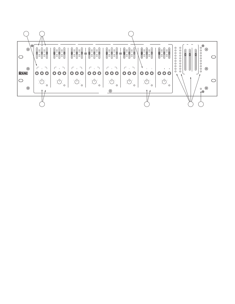
1
Mic/Line Input LEVEL controls 1-6
determine the amount of signal to be delivered to the assigned Outputs. The Overload
light monitors the signal level before and after the Equalizer. If this illuminates steadily, turn down the LEVEL or EQ controls to
prevent distortion.
2
Mic/Line Output ASSIGN
buttons. When the A button is engaged, the Mic/Line Input’s audio is routed to Output A.
When the B button is engaged, the Input’s audio is routed to Output B. When the AUX button is engaged, the Input’s audio is
routed to the Aux Output. Any (or all) of the ASSIGN buttons can be engaged simultaneously.
3
Equalizer controls
are used to contour the frequency response of the desired Input. LOW affects frequencies below 300 Hz,
MID affects 300 Hz to 3.3 kHz, and HIGH affects frequencies above 3.3 kHz. The Equalizer sounds best and potential overload
is avoided when at least one of the three bands is set to cut (below 0).
4
Stereo Line INPUT LEVEL controls 7/8 and 9/10
determine the amount of stereo or mono line signal to be delivered to the
assigned Outputs. The Stereo Line Overload light monitors the signal levels after the Equalizer and after the line gain stage. If this
illuminates steadily, turn down the LEVEL or EQ controls to prevent distortion.
5
Stereo Line Output ASSIGN buttons.
When the A/B assign button is engaged and the MONO button is not engaged, Input 7
(or 9) is routed to the A Output, while Input 8 (or 10) is routed to the B Output. When both the A/B ASSIGN and MONO but-
tons are engaged, both Inputs of 7 and 8 (or 9 and 10) will be routed to both the A and B Output. The AUX ASSIGN button is a
mono mix of the stereo Inputs.
6
A, B and AUX OUTPUT LEVEL controls
set the Output Level for A, B and AUX Outputs. The Output Meters indicate the
overall levels of Output A, Output B and the AUX Output. The Meters are “peak hold”.
7
POWER indicator
lights whenever adequate power is applied to the unit.
-
12
0
+
12
-
12
0
+
12
-20
-10
MIC / LINE
MIXER
+2
-7
-4
0
-2
+7
+4
+10
-20
-10
+2
-7
-4
0
-2
+7
+4
+10
2
1
5
3
4
6
7
10
8
9
2
1
5
3
4
6
7
10
8
9
10
0
2
4
8
6
-
12
0
+
12
-
12
0
+
12
10
0
2
4
8
6
-
12
0
+
12
-
12
0
+
12
10
0
2
4
8
6
-
12
0
+
12
-
12
0
+
12
10
0
2
4
8
6
-
12
0
+
12
-
12
0
+
12
10
0
2
4
8
6
-
12
0
+
12
-
12
0
+
12
10
0
2
4
8
6
-
12
0
+
12
-
12
0
+
12
10
0
2
4
8
6
10
0
2
4
8
6
-
12
0
+
12
-
12
0
+
12
ASSIGN
A
B
LOW
HIGH
MID
INPUTS
ASSIGN
MONO
A / B
POWER
OUTPUTS
1
2
3
4
5
6
7 / 8
9 / 10
A
B
AUX
MLM 103
LEVEL
OL
AUX
AUX
ASSIGN
A
B
LOW
HIGH
MID
LEVEL
OL
AUX
ASSIGN
A
B
LOW
HIGH
MID
LEVEL
OL
AUX
ASSIGN
A
B
LOW
HIGH
MID
LEVEL
OL
AUX
ASSIGN
A
B
LOW
HIGH
MID
LEVEL
OL
AUX
ASSIGN
A
B
LOW
HIGH
MID
LEVEL
OL
AUX
LOW
HIGH
MID
LEVEL
OL
ASSIGN
MONO
A / B
AUX
LOW
HIGH
MID
LEVEL
OL
1
3
2
4
6
7
5