Rane MLM 103 2000 version User Manual
Page 2
Manual-2
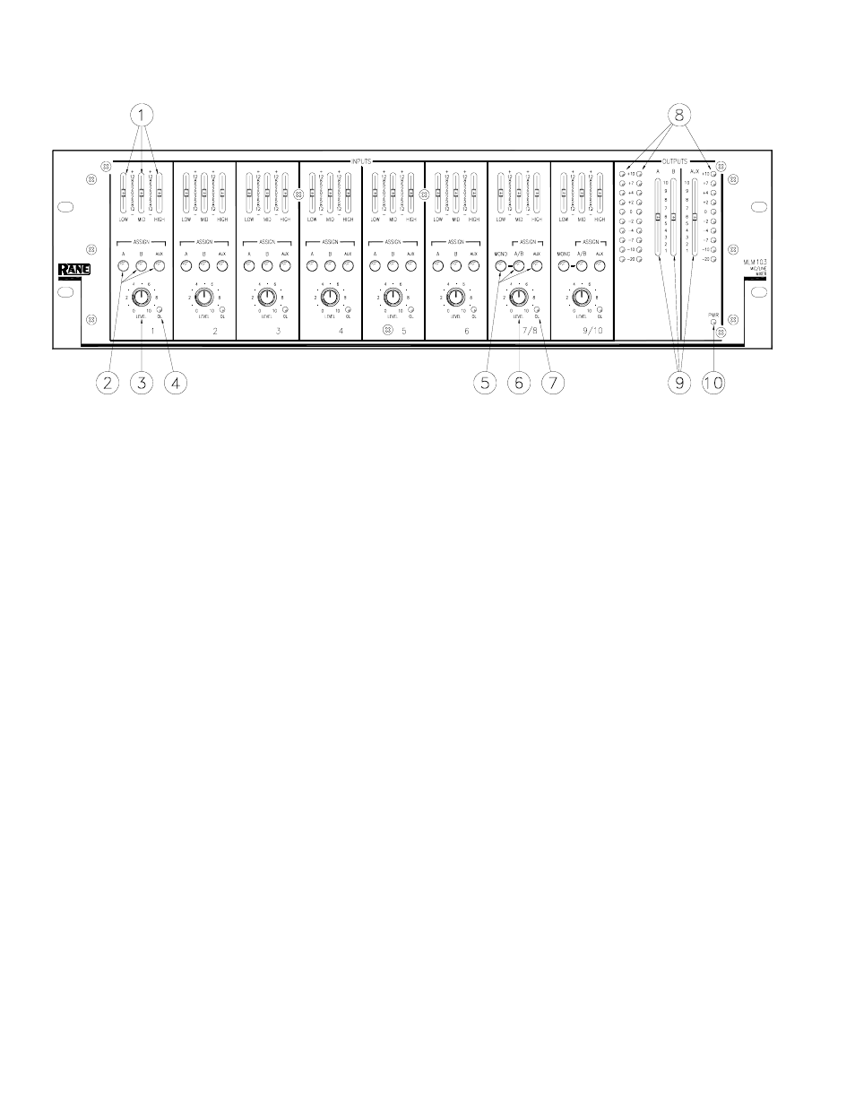
FRONT PANEL DESCRIPTION
ቢ Equalizer level controls are used to contour the frequency response of the desired Input.
ባ Mic/Line OUTPUT ASSIGN buttons. When the A button is engaged, the Mic/Line Input’s audio is routed to Output A.
When the B button is engaged, the Mic/Line Input’s audio is routed to Output B. When the AUX button is engaged, the Mic/
Line Input’s audio is routed to the Aux Output. Any (or all) of the ASSIGN buttons can be engaged simultaneously.
ቤ Mic/Line INPUT LEVEL controls 1-6 determine the amount of signal to be delivered to the assigned Outputs.
ብ Mic/Line OVERLOAD LED monitors the signal level before and after the Equalizer.
ቦ Stereo Line OUTPUT ASSIGN buttons. When the A/B assign button is engaged and the MONO button is not engaged,
Input 7 (or 9) is routed to the A Output, while Input 8 (or 10) is routed to the B Output. When both the A/B ASSIGN and
MONO buttons are engaged, both Inputs of 7 and 8 (or 9 and 10) will be routed to both the A and B Output. The AUX
ASSIGN button is a mono mix of the stereo Inputs.
ቧ Stereo Line INPUT LEVEL controls 7/8 and 9/10 determine the amount of stereo or mono line signal to be delivered to
the assigned Outputs.
ቨ Stereo Line OVERLOAD LED monitors the signal levels after the Equalizer and after the line gain stage.
ቩ Output Meters indicate the overall levels of Outputs A, B and the AUX Output. The Meters are “peak hold”.
ቪ A, B and AUX OUTPUT LEVEL controls set the Output Level for A, B and AUX Outputs.
ቫ POWER LED lights whenever adequate power is applied to the unit.