Operators manual me 60, Manual-1, Micrographic equalizer me 60 connection – Rane ME 60 2003 version User Manual
Page 3: Quick start
Manual-1
OPERATORS MANUAL
ME 60
microGRAPHIC EQUALIZER
ME 60 CONNECTION
When first connecting the ME 60 to other components, leave
the POWER switch off until the very last. This gives you a chance
to make mistakes and correct them without damaging your
fragile speakers, ears and nerves.
INPUTS
All three Inputs are wired in parallel and are actively bal-
anced, except the unbalanced RCA phono. Each works equally
well. Choose strictly from a required hardware point-of-view,
there will be no performance trade-offs. The wiring convention
adheres to American, British and International standards of pin
2 or tip being hot, pin 3 or ring being return, and pin 1 or sleeve
being shield. It is not necessary to short any inputs to ground—it
doesn’t hurt, it’s just not necessary. Use pin 1, or the shell, for
shield ground. Unbalanced operation involves using only pin 2
or tip as signal, and pin 1 or sleeve as shield and ground.
OUTPUTS
The Outputs mimic the Inputs. Balanced output requires
using pin 2 or tip, and pin 3 or ring for the signal. It does not
require pin 1 or shield. The signal exists differentially between
the two balanced leads; ground is not involved. For hum-free
systems ground is used only for shielding.
EXPANDING
Expanding and/or daisychaining the Inputs and Outputs
normally uses the ¼" jacks. Three parallel Input connectors
allows driving a second signal processor or amplifier without
special cabling.
SIGNAL LEVELS
Signal levels from -10 dBV to +4 dBu are considered normal
and within range (at least 20 dB of headroom exists above these
levels). Do not directly connect microphones into the ME 60.
These require a separate mic preamp.
QUICK START
Okay, know-it-all. So you don’t need to read the manual. Well do your mother a favor and just read this section and you don’t
have to read anything else. Ever.
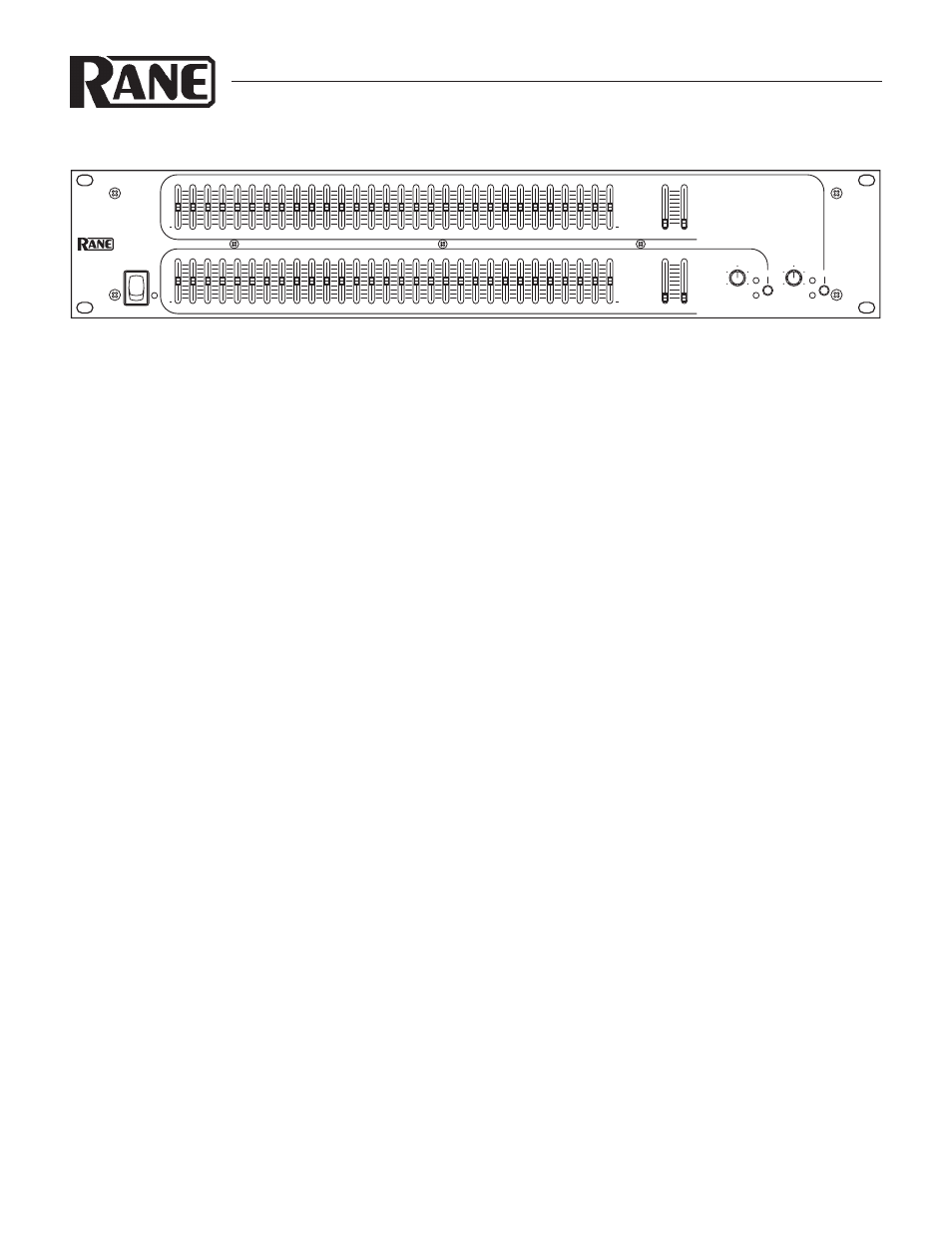
Hook-up is intuitive. Just follow the silkscreened instructions on the rear of the unit. All three Inputs are wired in parallel (they
do not sum); and all three Outputs are wired in parallel. Use any one Input and any or all Outputs. Polarity convention is per IEC/
ANSI/AES standards of pin 2 positive, pin 3 negative and pin 1 shield. The ME 60 does not invert the signal.
Set the LOW and HIGH CUT FILTER controls as necessary to restrict bandwidth. Full frequency response results from posi-
tioning them all the way to the bottom.
Anyone familiar with other graphic equalizers finds the ME 60 just as familiar. Setting curves is as easy as it is on all Rane graph-
ics thanks to our innovative constant-Q circuitry. If you feel you want more information on setting up your curves, please see the
back page.
There, now was that so bad?
WEAR PARTS
This product contains no wear parts.
10
40
15
150
30k
40k
10k
5k
250
3k
10
40
15
150
30k
40k
10k
5k
250
3k
0
+
12
•
6
•
•
•
6
12
0
+
12
•
6
•
•
•
6
12
0
+
12
•
6
•
•
•
6
12
0
+
12
•
6
•
•
•
6
12
10
0
2
4
8
6
10
0
2
4
8
6
MICROGRAPHIC
EQUALIZER
ME 60
BYPASS
LEVEL
OL
BYPASS
LEVEL
OL
2
1
HIGH
LOW
HIGH
LOW
CUT FILTERS
CUT FILTERS
400
31.5
25
40
63
50
100
80
160
125
250
200
315
12.5k
1k
630
500
800
1.6k
1.25k
2k
3.15k
2.5k
5k
4k
8k
6.3k
10k
20k
16k
400
31.5
25
40
63
50
100
80
160
125
250
200
315
12.5k
1k
630
500
800
1.6k
1.25k
2k
3.15k
2.5k
5k
4k
8k
6.3k
10k
20k
16k
POWER