Front panel description – Rane FPM 42 User Manual
Page 2
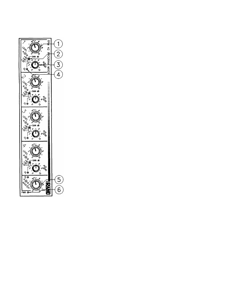
FRONT PANEL DESCRIPTION
1. INPUT LEVEL CONTROLS. These concentric level controls set the level of each
input to be routed to the Master A/B outputs and buses. The inner knob controls the level
to be sent to A, the outer knob controls the signal applied to B. Rotating the knobs
together creates a “pan centered” effect. Leaving one off and increasing the other emu-
lates a full pan to one side.
2. GAIN SELECT SWITCH. These switches set the maximum gain of the input stages in
each of the four input sections. The 60 dB mode is normally used for most microphones.
The 40 dB mode would be used for high level microphones or very weak line level inputs.
The 20 dB mode is suitable for line level inputs.
3. AUX SEND LEVEL CONTROL. There is only one of these for both the AUX A and
B sends. It controls the amount of channel input fed equally to the optional A and B Aux
outputs. This control’s range is from Off to +10 dB. The Aux source is selected from
either pre- or post fade via internally located switches.
4. OVERLOAD INDICATOR This red LED comes on anytime the input amplifier ex-
ceeds a level of 4 dB below clipping.
5. MASTER A & B LEVEL CONTROLS. These concentric knobs set the signal output
level of the Master A output (inner knob) and the Master B output (outer knob). Their
range is from Off to +10 dB.
6. POWER INDICATOR. Indicates power, as indicated.