Rear panel description – Rane FLM 82 User Manual
Page 3
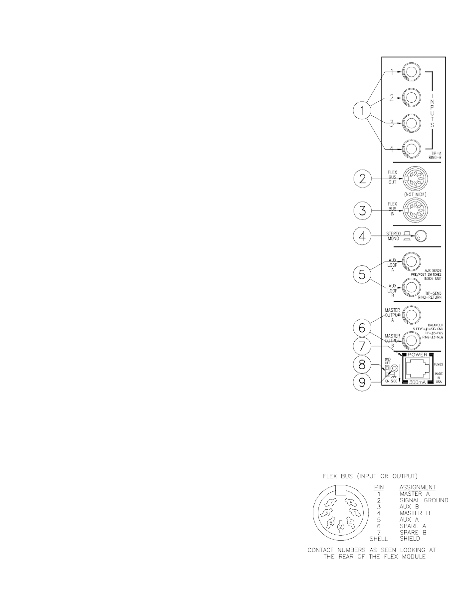
REAR PANEL DESCRIPTION
1. LINE INPUTS. These are the four main stereo inputs to the FLM 82. The
tip of each connects to the respective Channel A input, the ring is used for
Channel B.
2. FLEX BUS OUT. This DIN connector supplies all local master A and B
program signal as well as the Aux A and B signals. It also sends any
information coming into the FLEX BUS IN connector on to other modules
further down the line.
3. FLEX BUS IN. This connector is used to tie other Flex Series mixing
modules to the FLM 82. Both master & aux program material from the FLM
82 is added to this BUS INPUT.
4. STEREO / MONO SWITCH. Engaging this switch causes the A and B
MASTER buses (local only, not the Flex Bus) and the Aux A and B buses to
be added together to create one signal from two. It may be used in instances
where only mono inputs are connected to the FLM 82 and two outputs (A
and B) are required on both MASTER and AUX Outputs. It may be also
used to convert a two channel program input to a mono output. This switch
affects only the direct outputs on the rear of the unit. It has no effect over
FLEX BUS INPUTS or FLEX BUS OUTPUTS.
5. AUX LOOPs A and B. Primarily designed to allow signal processing to be
inserted in the Aux buses, these jacks may also be used for direct Aux
Outputs should the need arise. See the System Connection section on the
front page of this manual for more information.
6. MASTER OUTPUTs A and B. These are TRS balanced jacks. The tip is
the pos connection, the ring is neg and sleeve is signal ground.
7. POWER INPUT CONNECTOR. USE ONLY A MODEL RS 1, FRS 8,
OR OTHER REMOTE AC POWER SUPPLY APPROVED BY RANE. The
FLM 82 is supplied with a remote power supply suitable for connection to
this input jack. Consult the factory for replacement or substitution.
8. GROUND LIFT SWITCH. This switch provides the ability to separate
chassis ground and signal ground. Normally, this switch should be in the
LIFT position. In some circumstances it may be necessary to move it to the
opposite position to eliminate stubborn hum and buzz problems. We realize
a scientific explanation of this switch would be helpful, unfortunately
science doesnt seem to have much to do with it. See the CHASSIS
GROUNDING note on the last page for details. If you are tempted to try
moving this switch with your power amplifiers turned on or turned up,
DONT BE. ALWAYS TURN YOUR AMPLIFIER LEVELS DOWN
BEFORE CHANGING YOUR GROUNDS AROUND and then bring them
up slowly.
9. CHASSIS GROUND POINT. A 6-32 screw is used for chassis ground-
ing purposes. See the CHASSIS GROUNDING note on the last page for
details.