Rear panel description – Rane FAC 28 User Manual
Page 3
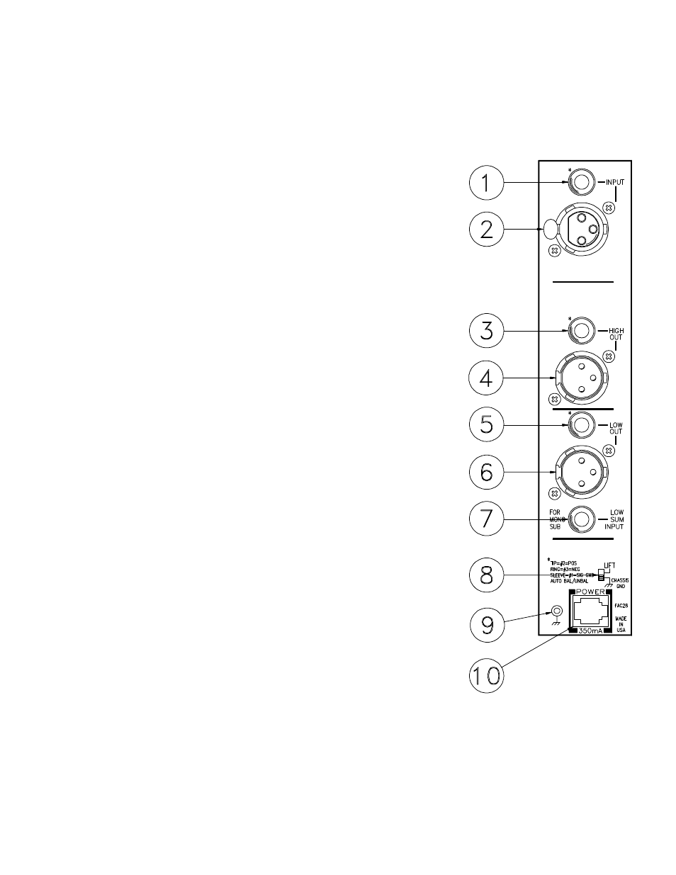
REAR PANEL DESCRIPTION
1. ¼" INPUT CONNECTOR. A balanced/unbalanced Input, the tip is positive, ring
is negative and sleeve is ground. For unbalanced operation, drive the tip as hot and
the sleeve as ground. The ring may be left open or shorted to sleeve. You may also
use a TRS or “mono” connector.
2. 3-PIN INPUT CONNECTOR. Pin 2 is positive, pin 3 is negative and pin 1 is
signal ground. For unbalanced operation, drive pin 2 as hot and 1 as ground.
3. ¼" HIGH FREQUENCY OUTPUT CONNECTOR. This ¼" TRS connector
parallels the 3-pin connector featured in item #4. Tip is positive, Ring is negative
and Sleeve is signal ground.
4. 3-PIN HIGH FREQUENCY OUTPUT CONNECTOR. Pin 2 is positive, pin 3
is negative and pin 1 is signal ground. For unbalanced operation, do not short any
pins to any others. Active balanced outputs operated in the unbalanced mode
should only consist of pin 2 driving the line and pin 1 acting as the return. Pin 3
should be left disconnected.
5. 1/4" LOW FREQUENCY OUTPUT CONNECTOR. This ¼" TRS connector
parallels the 3-pin connector featured in item #6. Tip is positive, Ring is negative
and Sleeve is signal ground.
6. 3-PIN LOW FREQUENCY OUTPUT CONNECTOR. Identical to item #4
above except this one sings the low parts.
7. LOW SUM INPUT CONNECTOR. This is an unbalanced Input consisting of
only a tip and sleeve contact. The tip is positive and the sleeve is ground. It is to
be used to connect the Low frequency Output of another crossover module so that
the Low Out of the driven unit consists of a mono sum of both Low frequency
sections. This is useful for mono sub woofer applications in a two channel (dare
we use the word stereo) system.
8. GROUND LIFT SWITCH. This switch provides the ability to separate chassis
ground and signal ground. Normally, this switch should be in the LIFT position. In
some circumstances it may be necessary to move it to the opposite position to
eliminate stubborn hum and buzz problems. We realize a scientific explanation of
this switch would be helpful, unfortunately science doesn’t seem to have much to
do with it. If you are tempted to try moving this switch with your power amplifiers
turned on or turned up, don't be. Always turn your amplifier levels down before
changing your grounds around and then bring them up slowly.
9. REMOTE POWER SUPPLY INPUT. The FAC 28 is supplied from the factory
with a Model RS 1 Remote Power Supply suitable for connection to this input
jack. The power requirements of the FAC 28 call for a 18-24 volt AC
center-tapped transformer only. It is not a telephone jack. Never use a power
supply other than the one supplied or an exact replacement approved by Rane
Corporation. Using any other type of supply may damage the unit and void the
warranty. Two years parts and labor is worth safeguarding, don’t you think?
10. CHASSIS GROUND SCREW. This 6/32 screw is provided to attach an external
earth ground to the system. This may be necessary in situations where no other
earth ground reaches the chassis of the processing components due to the fact that
the third pin earth ground of the line cord does not pass through the external
power supply. If the rack rails are not earth grounded by some other means, one of
the FLEX components in your system may require that this connection be made
for safety purposes and noise performance. Tip: connecting this point to the power
amplifer chassis solves most grounding problems.