Front panel description – Rane FAC 28 User Manual
Page 2
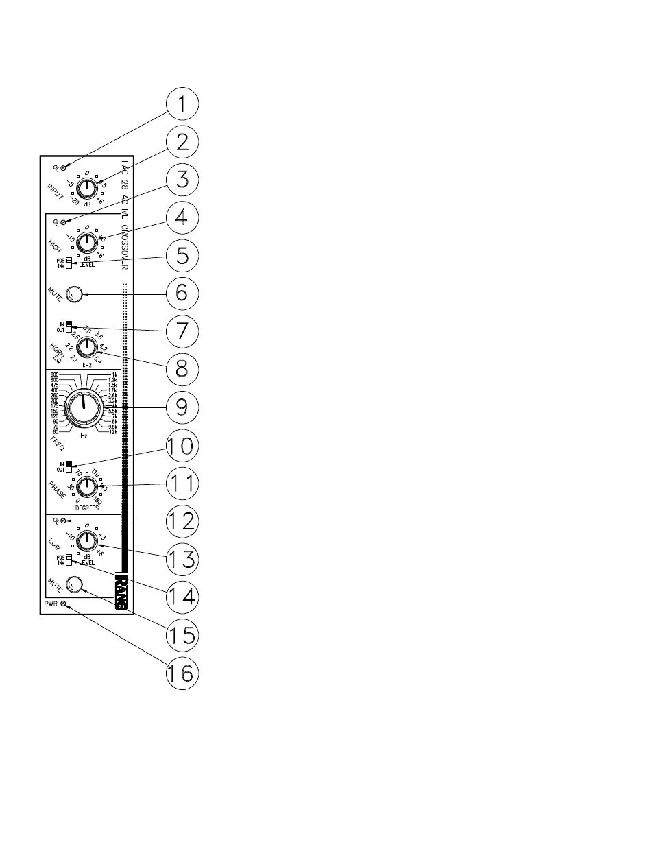
FRONT PANEL DESCRIPTION
1. INPUT OVERLOAD INDICATOR. This red LED will illuminate any time the
input stage is driven to within 4dB of clipping. This level is a function of both
input signal level and the position of the input gain control.
2. INPUT LEVEL CONTROL This rotary control determines the input gain of
the crossover. Its range is from -20dB to +6dB. The majority of applications
should find this control set at 0dB for unity gain.
3. HIGH OUTPUT OVERLOAD INDICATOR. This red LED will illuminate
anytime the high frequency output of the crossover is driven to within 4dB of
clipping. This level is a function of both the INPUT level and the HIGH fre-
quency output LEVEL control.
4. HIGH OUTPUT LEVEL CONTROL. This rotary control determines the
amount of gain to follow the high frequency output of the crossover’s frequency
dividing network. Its range covers OFF to +6dB.
5. HIGH FREQUENCY INVERT SWITCH. This two position slide switch
electrically inverts the high output in the INV position. This may be necessary
where drivers or amplifiers are wired incorrectly or when the crossover’s phase
control lacks sufficient range (more that 180 degrees becomes necessary).
6. HIGH FREQUENCY MUTE SWITCH. In its in position, all output signal
from the High Output of the crossover will be totally muted. This is to be used
when initially setting Levels of the Low Output and during the Phase alignment
process.
7. HORN EQ DEFEAT SWITCH. If a constant-directivity horn is to used on the
High Output, set this switch to the IN position.
8. HORN EQ FREQUENCY CONTROL. This rotary control allows a continu-
ously variable adjustment of the frequency at which boost begins to occur. This
should be set based on the horn manufacturer’s recommendation.
9. CROSSOVER FREQUENCY SELECTOR. This rotary control offers 24
precise frequencies at which the crossover makes the divide between the High
and Low Outputs. It is a binary encoding switch which sets up the digital control
of the filter’s frequency dividing circuits for very high precision.
10. PHASE CONTROL BYPASS SWITCH. In its OUT position, the phase
control has no effect on the low frequency output.
11. PHASE ANGLE CONTROL. This rotary control provides a constantly
variable 0 to 180 degree phase shift between the Low and High Outputs.
12. LOW FREQUENCY OVERLOAD INDICATOR This red LED illuminates
any time the Low Output comes within 4dB of clipping. This level is a function
of INPUT level as well as LOW frequency Output LEVEL.
13. LOW FREQUENCY LEVEL CONTROL. This rotary control varies the
output gain of the LOW frequency section from OFF to +6dB.
14. LOW FREQUENCY INVERT SWITCH. This switch electrically inverts the
polarity of the low output in the INV position. This may be necessary for many
of the same reasons cited in #5, above.
15. LOW FREQUENCY MUTE SWITCH. Identical to #6 above, with the
exception that it Mutes the Low Output.
16. POWER INDICATOR Illuminates whenever the correct AC power is applied
to the unit from a remote power supply.