Deq 60 / deq 60l, Operators manual, Manual-1 – Rane DEQ 60 User Manual
Page 3: Graphic equalizer, Quick start, Wear parts: this product contains no wear parts
Manual-1
DEQ 60 / DEQ 60L
GRAPHIC EQUALIZER
OPERATORS MANUAL
WEAR PARTS: This product contains no wear parts.
GRAPHIC
EQUALIZER
6
3
3
6
∞
6
∞
6
20k
7k
14k
5k
10k
15
120
30
240
60
∞
6
∞
6
20k
7k
14k
5k
10k
15
120
30
240
60
6
3
3
6
•
•
•
•
•
•
•
•
+6
-12 -6
-3
0
+3
+12 OL
+6
-12 -6
-3
0
+3
+12 OL
0
+
0
+
12
12
12
12
12
12
12
12
+
+
0
+
0
+
0
0
+
+
0
+
0
+
0
0
±6
±6
5.0k
25
31.5
40
50
63
80
100
800
125
160
200
250
500
400
315
630
2.0k
1.25k
1.0k
1.6k
3.15k
2.5k
4.0k
12.5k
8.0k
6.3k
10k
16k
20k
LOW MID HIGH
LOW HIGH
IN
OUT
POWER
B
EQ
EQ
PROPORT-Q
OUT
IN
PERFECT-Q™
BYPASS
A
±12
CUT FILTERS
TONE
LEVEL
DEQ 60
A
B
A
B
B
PROPORT-Q
OUT
IN
PERFECT-Q™
BYPASS
A
±12
12
6
6
12
12
6
6
12
+
0
+
0
•
•
•
•
•
•
•
•
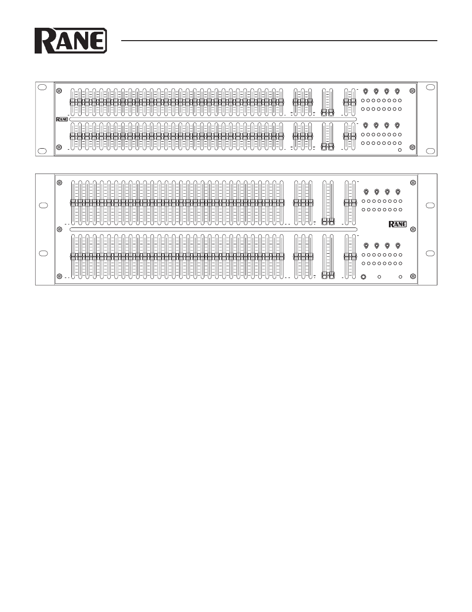
QUICK START
We know you know how to use an equalizer. Just read this sec-
tion for the unique things to be aware of in the DEQ 60 and
DEQ 60L.
Both units have the same features, in short and long throw
versions. One exception: the DEQ 60L’s CUT-ONLY mode.
Activating this switch puts both equalizer channels in the high
resolution CUT 0 to -12 dB (gray number scale).To prevent
unwanted sudden volume shifts when switched, the DEQ 60L
outputs mute for a moment, then slowly increases in volume.
We know you know how to use a realtime analyzer, but using
PERFECT-Q
mode will make that job a lot easier. Since there is
no interaction between filters, the multiple adjustments through
all the bands just to get the analyzer to read flat is a thing of the
past. One pass should do the trick. Then use the TONE controls
or CUT FILTERS for general sweetening. We know your sound
is important and your time is valuable.
If you want to compare the sound of your old (non-Rane)
EQ to this one, and you are used to the way the slider bands
interact, then use PROPORTIONAL-Q mode.
The A and B switches are like memories or control assigns.
GRAPHIC EQUALIZER
∞
6
7k
14k
5k
10k
20k
15
120
30
240
60
+6
-12 -6
-3
0
+3
+12 OL
+6
-12 -6
-3
0
+3
+12 OL
12
12
12
12
+
0
+
0
+
0
∞
6
7k
14k
5k
10k
20k
15
120
30
240
60
12
12
12
12
+
0
+
0
+
0
CUT-ONLY
12
4
8
5
7
3
2
10
1
11
9
0
6
CUT
12
4
8
5
7
3
2
10
1
11
9
0
6
CUT
6
2
4
•
•
•
1
5
•
•
•
0
3
CUT
6
2
4
•
•
•
1
5
•
•
•
0
3
CUT
5.0k
25
31.5
40
50
63
80
100
800
125
160
200
250
500
400
315
630
2.0k
1.25k
1.0k
1.6k
3.15k
2.5k
4.0k
12.5k
8.0k
6.3k
10k
16k
20k
LOW MID HIGH
LOW HIGH
IN
OUT
POWER
B
EQ
EQ
PROPORT-Q
OUT
IN
PERFECT-Q™
BYPASS
A
±12
CUT FILTERS
TONE
LEVEL
DEQ 60L
A
B
A
B
B
PROPORT-Q
OUT
IN
PERFECT-Q™
BYPASS
A
±12
12
4
4
2
2
6
8
8
10
10
6
12
0
+
12
4
4
2
2
6
8
8
10
10
6
12
0
+
±6
±6
6
2
2
1
1
3
4
4
5
5
3
6
0
+
6
2
2
1
1
3
4
4
5
5
3
6
0
+
Normal stereo use would set the top row A (Left), and the bot-
tom row to B (Right). But if you are running in stereo, and both
sides use the same EQ curve, you can set both switches to A.
Now the top EQ curve controls both left and right channels.
Switching these to B will use the bottom EQ curve for both
channels. This is great for switching EQ when a source changes.
Just be aware of where these switches are, an unassigned EQ row
will have no audible effect. These switches also affect the CUT
FILTERS
, TONE CONTROLS, and LEVELS.
The channel BYPASS switches have two modes, set by the
rear panel switch. When set to FILTERS, the BYPASS switch
only bypasses the EQ, TONE and CUT FILTERS. The LEVEL
controls and other switches remain active. When set to ALL,
the BYPASS switches ignore everything including the LEVEL
controls.
You have several connector choices on the rear. However, use
only ONE type of INPUT on each channel. These Inputs do not
sum. But you may use any combination of OUTPUTS simulta-
neously if desired. Polarity convention on the XLR jacks is pin 2
positive, pin 3 negative and pin 1 shield (chassis ground).