Manual- zr 1 remote installation, Cp 52 audio connections – Rane CP 52 2003 version User Manual
Page 6
Manual-
ZR 1 Remote Installation
The CP 52 supports a wired remote for Zone Level and Zone
Source selection. Wire lengths of up to 1000 feet (300 meters) are
possible. A brief list of suitable wire types is provided here in the
Wire Types section.
The ZR 1 remote provides Zone Level and Source Selection,
allowing local control from inside the Zone. If only one of the
two controls is used, you may wish to remove the unused knob
and cover the hole with one of the plugs provided in the kit. If
you require one ZR 1 remote to control more than one unit, sim-
ply wire the ports in parallel. This may be done with the Selector
only, Level only or both.
Be sure Power to the CP 52 is off while all
remote connections are made. It is impor-
tant to ensure that the CP 52 Remote Port
is not subjected to sustained voltages outside
the range of 0 to 5 volts DC or high levels
of static. Inputs are protected—however,
caution is the better part of... you know. It is
a good idea to install the wiring, connect it
to the remote assemblies and then make the
final connections at the CP 52. Do not short
the Vr pin to ground. Although the pin is
CP 52 Audio Connections
All Input and Output connections are made with Euroblock
connectors except for the RCA Program Inputs. When wiring to
Euroblocks, a minimum wire gauge of 22 is preferred for reliabil-
ity. If the ground or shield wire is left shorter, it acts as a strain
relief for the other wires. Cable with a flexible jacket is easier to
use and less likely to damage the connections. Avoid stripping
excess insulation. Inspect wires for nicks that may lead to wire
breakage. Fully insert each wire in the appropriate socket and
tighten the screw.
The Page Input is a true instrumentation amplifier and oper-
ates balanced or unbalanced. Expand and Zone Outputs are
driven by high quality cross-coupled line drivers and operate bal-
anced or unbalanced. Wiring is usually the same for both Inputs
and Outputs. Balanced operation is recommended. Balanced
wiring is logical, (+) to (+), (–) to (–) and shield to shield.
For unbalanced operation, we recommend using two conduc-
tor cable with shield. The cable is wired to the CP 52 the same
as for balanced operation. At the other end of the cable, connect
the (+) wire to signal “hot,” and both the (–) and shield wires to
ground (important).
If you use single conductor cable with shield, connect the
shield/gnd wire to both the (–) and shield pins at the CP 52. At
the other end of the cable connect the (+) wire to the signal “hot”
and the shield/gnd wire to ground. When unbalanced wiring
is used, it is very important for the CP 52 and any other unit
in the system to have good earth or technical grounds. If a unit
is located far from the CP 52 or is of a type that might create
grounding problems, use isolation transformers.
When connecting any CP 52 Output as unbalanced, use (+)
and ground — leave (–) floating.
Refer to the included RaneNote, “Sound System Interconnec-
tion” for more information on proper wiring procedures.
current limited, excess heat will be generated in the 5 volt supply
if a short occurs. Never subject the Vr pin to voltages above 5V.
If a ZR 1 remote is not used, any simple switch closure to
GND will work for the D0 and D1 pins. These pins are TTL
compatible (0 to 5 VDC). The logic is inverse Gray Code. Any
ground referenced 5 volt DC control may be used as the input to
Vc. Do not ground the Vr pin.
Remote Selector
Remote Volume
11=LINE 1
2 kΩ pot, reverse-log taper
10=LINE 2
Or any GND referenced 0-5 VDC.
00=LINE 3
Attenuation=64 mV/dB.
01=PRIORITY
Range 0V to +5V (0 to -87 dB).
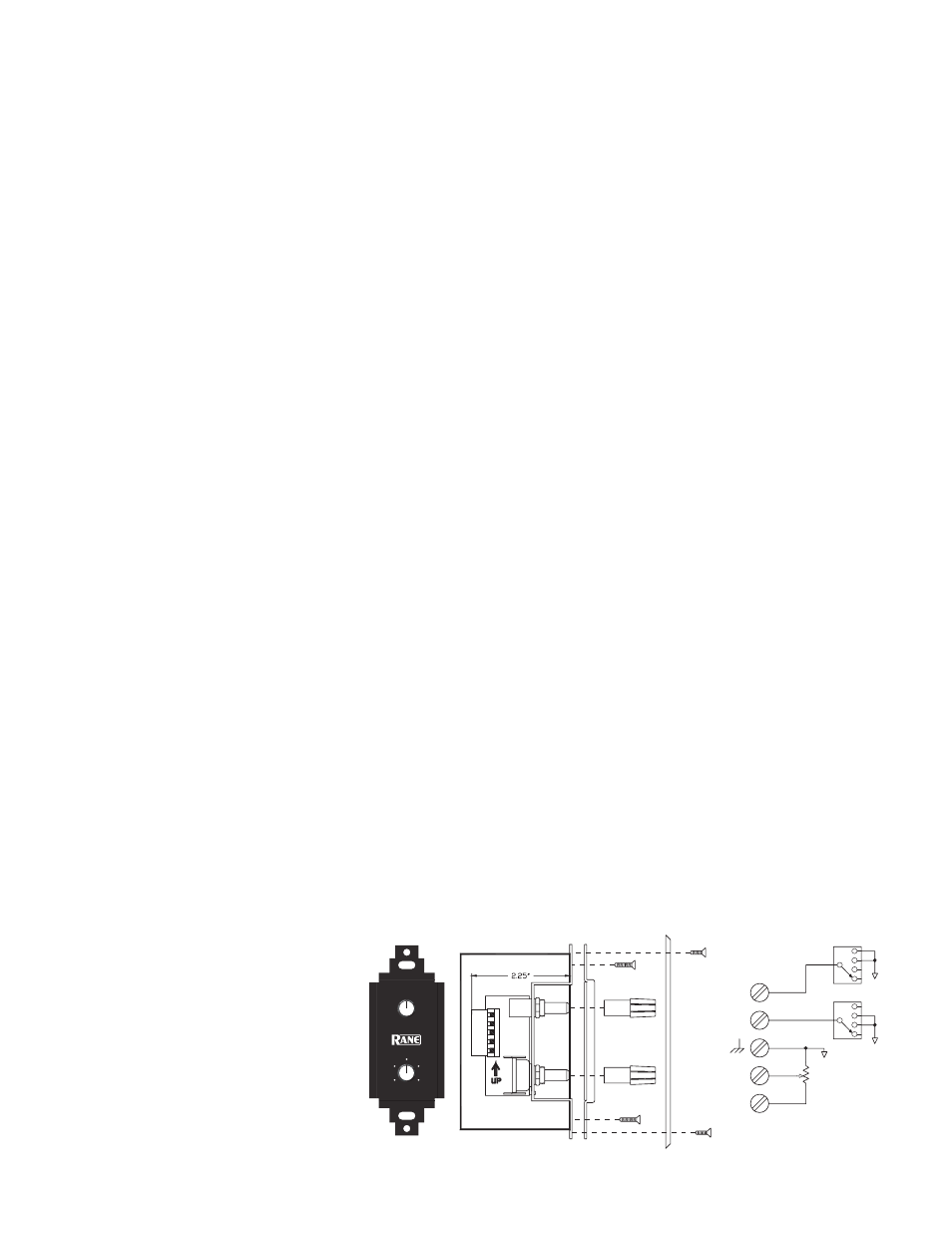
ZR 1 REMOTE MOUNTING
The ZR 1 remote assembly mounts in a standard U.S. electri-
cal box with a minimum depth of 2.25". Be sure to note the
wire color of each input in order to facilitate correct wiring to
the CP 52. Connect each wire to the 5-pin connector by fully
inserting it in the correct socket and tightening the screw. Make
sure the cable jacket is stripped back sufficiently to allow it to lie
in the electrical box with the remote assembly inserted. Use the
flat head #6 screws supplied with the kit to mount the remote
assembly and silk-screened front panel to the electrical box (see
diagram, next page). Note the “UP” arrow screened on the
printed circuit board of the remote (mount it pointing up).
The silkscreened front panel metal is painted on both sides.
This allows you to custom silk-screen the panel or add your own
custom decals. Simply install the modified front panel with your
art facing out.
Install each knob so that the line on the knob is properly
aligned with the silk-screening on the front panel of the remote
assembly. Install any Decora plate of your choice. For a secured
installation, you may wish to leave the knobs off and use a blank
Decora plate to cover the remote after adjustment.
WIRE TYPES
Variations in wire type do not greatly affect the performance
of the remote controls. However, 22-gauge stranded wire with
a flexible jacket is recommended. You may use 5-conductor
unshielded remote control signal cable for shorter runs (less than
200 feet [60 meters]) or 4-conductor (2 pair) shielded remote
control signal cable (use the shield as the ground return) for
longer runs (200 to 1000 feet [60 to 300 meters]). The type of
wire required is influenced by your installation and local electri-
cal codes.
PROGRAM SELECT
LEVEL
8
2
10
0
4
6
L1
L3
L2
P
D
ec
or
a
p
la
te
(n
ot
in
cl
ud
ed
)
1
2
3
4
5
S1A
6
7
8
9
10
S1B
2
3
4
1
5
J1A
5 POS TERM
GND
GND
GND
D1
D0
Vc
Vr
ZONE REMOTE (ZR 1)
C
W
2
1
3
R1
2KRD