Manual- rear panel description – Rane CP 52 2003 version User Manual
Page 5
Manual-
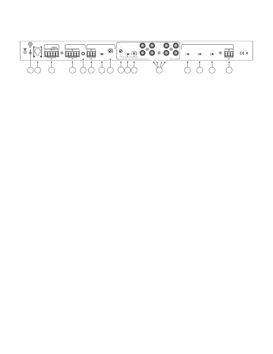
Rear Panel Description
1
Chassis Ground Screw
provides a convenient earth (technical) ground connection point. The CP 52 does not ground the chassis
through the power cord. It is important that the unit be grounded.
2
POWER
jack accepts the cable from a Rane RS 1 remote power supply (included). This is not a telephone jack. Use of a supply not
approved by Rane may damage the unit and void the warranty. Be sure the power to the CP 52 is OFF until all connections are made.
3
ZONE REMOTE
Port provides the wiring interface for the optional ZR 1 wired remote. The ZR 1 remote provides remote con-
trol of Zone Level and Zone Program Select functions. Refer to page Manual-4 for details.
4
ZONE OUTPUT
Port features a balanced line driver with a Euroblock connector. These Left and Right Outputs may be wired
balanced or unbalanced.
5
MONO
switch, when pressed in, sums the left and right signals to provide a mono Zone signal available at both Left and Right
Outputs.
6
EXPAND OUTPUT
features a balanced line driver with a Euroblock connector. This mono Output may be wired balanced or
unbalanced.
7
EXPAND switch
assigns PAGE-only, PROGRAM-only or full ZONE (both) as the source for the Expand Output.
8
EXPAND LEVEL
trim adjusts the signal level delivered to the ZONE EXPAND OUTPUT.
9
PRIORITY RELEASE TIME
control sets the delay time from last detected signal to release of automatic priority override. The
range of control is 5 seconds (ccw) to 20 seconds (cw).
0
PRIORITY OFF/ON
switch allows disabling the automatic priority override function when in the OFF position.
q
PRIORITY DETECT THRESHOLD
control allows adjusting the threshold from -∞ (signal on) to -35 dBu (typ). The factory
setting is -50 dBu.
w
Four PROGRAM INPUTS are provided. Three are non-priority Inputs — the fourth is a Program PRIORITY Input. When
signal is detected at this Input, it is automatically selected as the Program Input source regardless of the front panel PROGRAM
SELECT setting.
e
PAGE LEVEL TRACKS ZONE LEVEL
switch, when ON, forces the Paging level to track the Zone level. When OFF, Paging
level and Zone level are independent.
r
LOW / HIGH CUT FILTER
switch, when IN, limits the bandwidth of the Paging Input from 100 Hz to 7 kHz, improving
intelligibility in some installations. The Paging detector is always bandlimited to 100 Hz to 7 kHz.
t
MIC PHANTOM POWER
switch, when ON, enables +15 volt Phantom Power to the PAGING INPUT connector. If the front
panel LINE switch is selected, Phantom Power is defeated.
y
PAGING INPUT
Euroblock connector may be wired balanced or unbalanced.
RANE CORP.
MADE IN U.S.A.
INPUT
POWER
LOW / HIGH
PAGE LEVEL
TRACKS
PHANTOM
MIC
–
–
+
OFF
IN
OUT
OFF
ON
PRIORITY
ON
CUT FILTER
100 Hz / 7 kHz
+15V
+
ZONE LEVEL
RELEASE
DETECT
TIME
SEC
LEVEL
RIGHT
LEFT
ZONE OUTPUT
EXPAND OUTPUT
ZONE REMOTE
OFF ON
PAGE
PROGRAM
–
–
–
–
+
–
–
+
+
ZONE
D1 D0
D1 D0
Vc Vr
CLASS 2 EQUIPMENT
MIN
+
+
+
THRESHOLD
MONO
CP 52
ACN 001 345 482
L
L
R
R
L1
L2
L3
PROGRAM INPUTS
PAGING INPUT
20
5
750mA
POWER
2
1
3
4
6
7
9 10 11
13
14
15
16
12
5
8