Rane CP 31 User Manual
Page 3
Manual-3
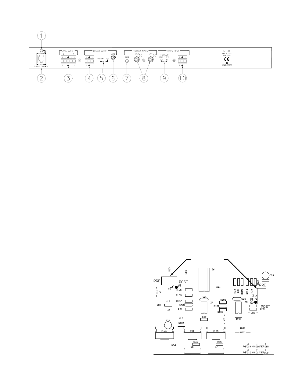
CP 31 - REAR PANEL
ቢ Chassis Ground Screw provides a convenient earth (technical) ground connection point. The CP 31 does not ground the
chassis through the power cord. It is important that the unit be grounded (required by law in most installations).
ባ POWER jack accepts the mod plug from a Rane RS 1 remote power supply (included) or an optional Rane RAP 10 power
supply. This is not a telephone jack. Use of a supply not approved by Rane may damage the unit and void the warranty.
ቤ ZONE OUTPUT Port features a balanced line driver with a Euroblock connector. These Left and Right Outputs may be
wired balanced or unbalanced.
ብ EXPAND OUTPUT Port features a balanced line driver with a Euroblock connector. This mono Output may be wired
balanced or unbalanced.
ቦ EXPAND OUTPUT switch assigns PAGE-only or PROGRAM-only as the source for the Expand Output.
ቧ EXPAND OUTPUT LEVEL trim adjusts the signal level delivered to the EXPAND OUTPUT.
ቨ PROGRAM INPUT MONO switch, when pressed in, sums the left and right Program signals to provide a mono signal
available at both A and B Zone Outputs. Mono program summing is before page summing, so A & B Paging Levels remain
independent when MONO is engaged.
ቩ PROGRAM INPUTS may be used as a stereo pair, or dual mono unbalanced sources.
ቪ PAGING INPUT HIGH/LOW CUT FILTER switch, when IN, limits the bandwidth of the Paging Input from 100 Hz to 7
kHz, improving intelligibility in some installations. The Paging detector is always bandlimited to 100 Hz to 7 kHz.
ቫ PAGING INPUT Euroblock connector may be wired balanced or unbalanced.
PAGE SUM SWITCHES
INTERNAL PAGING PRE/POST ZONE LEVEL
SWITCHES
As shipped from the factory, the Zone LEVEL controls on
the front of the CP 31 only control Program level, so Page
volume will always be heard as set by the PAGING LEVEL
controls. The internal Paging Pre/Post Zone Level switches
are shipped from the factory in the POST position. If desired,
the switches may be set to PRE, allowing the Zone LEVEL to
control both Program and Page, mixing mic and line.
To change these switches, be sure power is disconnected.
Remove the top cover of the unit and locate the switches on
the circuit board as shown to the right. Replace the top cover.