Rear panel description – Rane CM 86 User Manual
Page 3
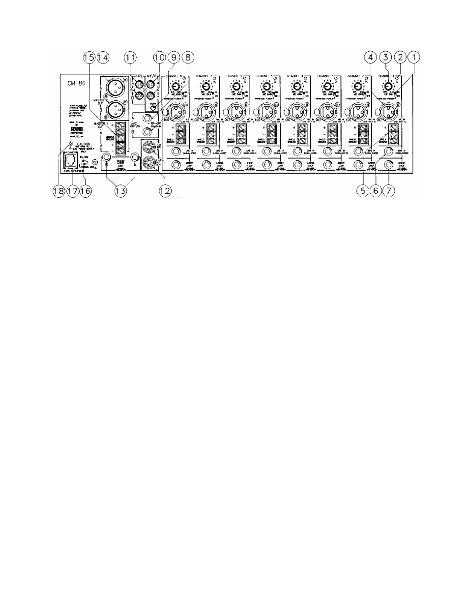
REAR PANEL DESCRIPTION
1. PHANTOM POWER SELECTOR SWITCH. Turns the microphone Phantom Power voltage ON and OFF.
2. INPUT OL (OVERLOAD) INDICATOR. This red LED is identical to one on the front panel and monitors all critical
input nodes. It lights when these levels exceed 4dB below clipping. Some flickering is normal; it should not light steadily.
3. MIC GAIN TRIM CONTROL. A rotary control used to set the correct gain required by your microphone.
4. 3-PIN MICROPHONE INPUT CONNECTOR. Pin 2 is positive, pin 3 is negative and pin 1 is signal and shield
ground. This connector is in parallel with the terminal strip below. USE ONLY ONE — THEY DO NOT SUM.
5. TERMINAL STRIP MICROPHONE INPUT CONNECTOR. Parallels the 3-pin connector above.
6. LINE INPUT CONNECTOR, 1/4" UNBALANCED (mono) input connector. Use for any line-level source. This input
is automatically grounded when not used.
7. INPUT CHANNEL INSERT LOOP. This jack allows any outboard unit to be patched in-series with the input signal.
LOCATED POST-EQ. Wired per standard tip=send/rimg=return convention. Automatically bypassed when not used.
8. AUX OUT/IN JACKS. A pair of UNBALANCED 1/4" TRS jacks used for either AUX OUT alone, or as a Send/Re-
ceive (Out/In) effects loop for recording and other applications. For AUX OUT, use a standard MONO unbalanced 1/4" plug
(the IN function is automatically grounded). For effects loop use, this jack follows the standard tip=send (out) / ring=receive
(in) wiring convention. Very clever (or desperate) users make use of this jack as a direct input to the Master summing net-
works. To do this, use a 1/4" TRS plug wired with the input signal going to the RING and leave the TIP open (unused).
9. TAPE/CD INPUT MONO PUSHBUTTON. Used to mono whatever source is connected to the RCA input jacks.
10. TAPE/CD RCA INPUTS JACKS. A pair of RCA jacks used to connect a Tape player, Tuner, CD player, or any line-
level source requiring this type of jack. Sums directly into the Aux and Master mixing buses via the Level controls on front.
11. TAPE OUTPUT RCA JACKS. A pair of RCA jacks used to connect a Tape Recorder. This output signal is located
AFTER the Master Insert Loops and BEFORE the Master Output Level controls.
12. FLEX BUS IN & OUT CONNECTORS. A pair of 7-pin DIN jacks used to expand to another CM 86, or to augment
input/output features by adding any of the Flex Modules using the Flex Bus. See the Rane FLEX USERS GUIDE for details.
13. MASTER INSERT LOOP JACKS. 1/4" TRS jacks wired tip=send/ring=return used to add any outboard effects unit
in series with all the Master Outputs. Located BEFORE the Tape Out jacks.
14. MASTER 2 A & B OUTPUT 3-PIN CONNECTORS. Pin 2 is positive, pin 3 is negative and pin 1 is signal ground.
Do NOT use pin 1 for true balanced interconnection; tie shield at one end ONLY. Unbalanced use requires grounding of pin
3, i.e., tie pin 3 to pin 1.
15. MASTER 1 A & B OUTPUT TERMINAL STRIP. Do NOT use COMMON GROUND for true balanced intercon-
nection; tie shield at one end ONLY. Unbalanced use requires grounding of negative (“–”) output, i.e., tie the “–” and COM-
MON GROUND terminals together.
16. GROUND LIFT SWITCH. Provides the ability to separate chassis and signal grounds. Do not move this switch with
your power amplifiers turned on and up.
17. REMOTE POWER SUPPLY INPUT. The unit is supplied with the large Model RS 2 Remote Power Supply. NEVER
USE A POWER SUPPLY OTHER THAN THE ONE SUPPLIED OR A REPLACEMENT APPROVED BY RANE COR-
PORATION.
18. CHASSIS GROUND POINT. Used for chassis grounding purposes. See CHASSIS GROUNDING on the last page for
details.