Front panel description – Rane CM 86 User Manual
Page 2
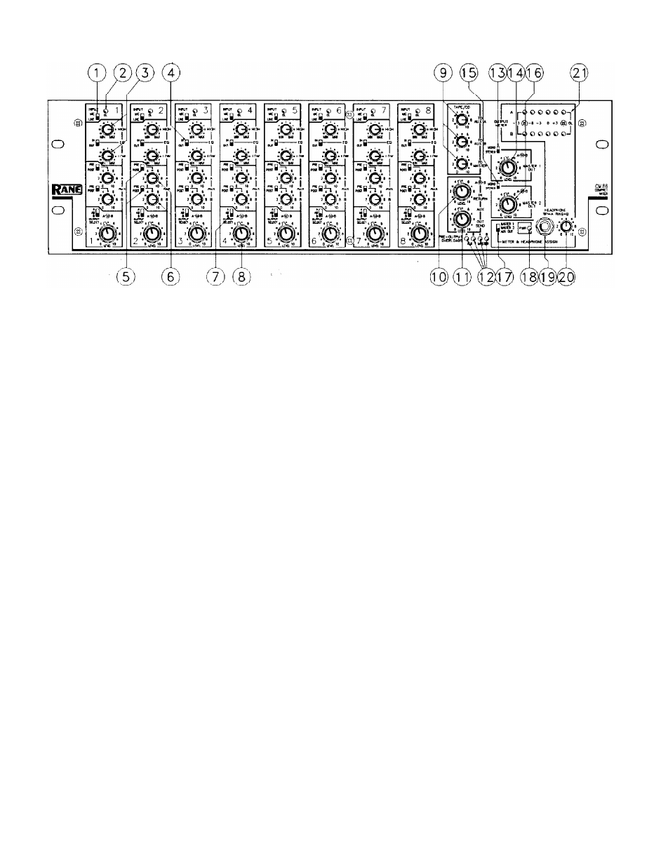
FRONT PANEL DESCRIPTION
1. INPUT SOURCE SELECTOR. This slide switch selects between MIC or LINE inputs. Both inputs may be used; in
which case this switch acts as a true source selector. If the LINE input is not used then it is internally grounded and this
switch acts like a Mic Mute when moved to the LINE position.
2. INPUT OVERLOAD INDICATOR. This red LED parallels an identical one in the rear and monitors all critical input
nodes. It lights whenever these levels exceed 4dB below clipping. Occasional flickering is normal; however., it should not be
allowed to light steadily.
3. INPUT EQUALIZATION CONTROLS. A two-band shelving LOW (bass) and HIGH (treble) tone control circuit.
These controls adjust the frequency contour of both MIC and LINE inputs. The EQ is located before the INSERT LOOP.
4. EQ IN/OUT ENGAGE SWITCH. This slide switch controls the EQ circuits. Useful for comparing equalized (IN) with
unequalized (OUT) signals, or for guaranteeing flat frequency response (OUT).
5. PRE/POST AUX-ASSIGN SWITCHES. These slide switches allow choosing the AUX take-off points. Selecting PRE
places the AUX Level before the Channel LEVEL controls, thus allowing independent operation between the two. Selecting
POST takes the AUX Level after the Channel LEVEL controls, thereby allowing the LEVEL controls to affect all outputs.
6. AUX CONTROLS. Separate controls for mixing the input channel into the AUX A and AUX B Output (Send) signals.
7. OUTPUT SELECT SWITCH. A three-position slide switch that selects routing of this input channel. Choosing either
“A” or “B” puts all of this signal into only the A or B outputs. Choosing “AB” puts this signal equally into both.
8. CHANNEL LEVEL A/B CONTROLS (Input Faders). Concentric controls used to set the amount of signal mixed into
the MASTER A and B outputs.
9. TAPE/CD MIX CONTROLS. Three rotary controls that set the amount of the Tape, Tuner, or CD input signals mixed
in with the AUX A, AUX B or MASTER outputs.
IO. AUX IN/RETURN LEVEL CONTROL. Concentric knobs that control the amount of AUX signal coming into the
AUX OUT/IN jacks (on the ring). Often the return path from an effects box in the AUX OUT/IN LOOP; or alternatively, it
may control a separate AUX input.
11. AUX OUT/SEND LEVEL CONTROL. Concentric knobs that control the amount of AUX signal coming out of the
AUX OUT/IN jacks (on the tip). Often the send path for an effect box in the AUX OUT/IN LOOP; or alternatively, it is the
AUX output level.
12. PRE-OUTPUT OVERLOADS. LED indicators monitoring the four critical summing stages (Master A/B and Aux
A/B). They light 4dB before actual clipping. Occasional blinking is okay, but do not allow them to light steady.
13. MASTER 1 OUT STEREO/MONO SWITCH. A slide switch used to mono the MASTER 1A & 1B outputs.
14. MASTER 1 OUTPUT LEVEL CONTROLS. Concentric controls used to set the desired output level.
15. MASTER 2 OUT STEREO/MONO SWITCH. A slide switch used to mono the MASTER 2A & 2B outputs.
16. MASTER 2 OUTPUT LEVEL CONTROLS. Concentric controls used to set the desired output level.
17. METER & HEADPHONE ASSIGN SWITCH. A three-position slide switch used to choose between MASTER
1A/1B, MASTER 2A/2B or AUX A/B outputs for monitoring by the OUTPUT METERS and HEADPHONE circuits.
18. POWER INDICATOR. A yellow LED that lights whenever proper power is applied to the CM 86.
19. HEADPHONE JACK. A standard 1/4" jack for stereo headphones. This allows headphone monitoring of whatever out-
put is selected. Standard wiring convention is followed, i.e., Tip=Left ear= Channel A, and Ring=Right ear=Channel B.
20. HEADPHONE LEVEL CONTROL. Used to set the desired headphones listening level.
21. OUTPUT METER. A two-channel 6-segment peak responding LED meter accurately calibrated in dBu units.