Rane AVA 22D 2000 version User Manual
Page 2
Manual-2
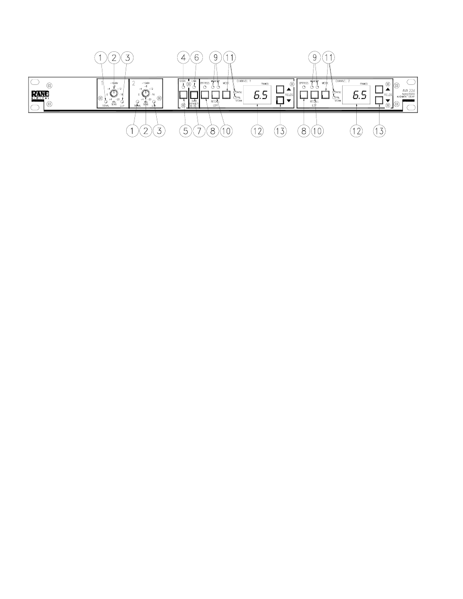
FRONT PANEL DESCRIPTION
ቢ SIGNAL indicators: These green LEDs illuminate approximately 42 dB before actual clipping.
ባ SENSITIVITY controls: These rotary controls vary incoming signal levels to the A to D converter. The output signal is
also adjusted so the AVA 22d always passes signal with unity gain into 600 ohm loads. (See operating instructions.)
ቤ CLIP indicators: These red LED indicators illuminate 4 dB before clipping at the A to D converter input.
ብ STORE indicator: This flashing LED indicator alerts the user that the current configuration of the AVA 22d is different
from the stored configuration. The STORE LED is off when the current configuration matches the stored configuration.
ቦ STORE button: This pushbutton stores both Channels’ current Delay configurations into the given Channels’ current
Memory (A or B). The current Memory for each Channel is indicated by the lit MEMORY LED for that Channel.
ቧ LINK indicator: This green LED lights when the unit is in LINK mode. LINK mode allows stereo operation.
ቨ LINK button: This pushbutton toggles between LINK mode (stereo operation) and DUAL MONO operation. (See Operat-
ing Instructions.)
ቩ BYPASS buttons and indicator: These momentary push buttons toggle each Channel’s hard-wired Bypass. If an LED is
on, the given Channel is Bypassed and functions like a wire. If it is off the given Channel is active.
ቪ MEMORY indicator: These LEDs indicate the most recently recalled Memory, A or B, for the given Channel. They also
indicate the Memory that is written to when the STORE button is pressed. The MEMORY LED flashes when the current
Delay value for that Channel is different than the stored value for that Channel.
ቫ RECALL buttons: Pressing one of these pushbuttons alternately Recalls stored Memories A and B for the given Channel.
ቭ MODE buttons and indicator: These buttons toggle the broadcast mode for the given Channel, NTSC or PAL/SECAM.
Each Channel contains LEDs indicating the current broadcast Mode.
ቮ FRAMES displays: These 2-digit displays indicate the current Delay value for the given Channel. On power up this display
also shows the currently installed software revision level.
ቯ UP/DOWN buttons: Pressing these buttons increases/decreases the amount of Delay in the given Channel.