Vermont castings ewf30, Installing the chimney system, Installing the firestop spacer in the ceiling hole – Vermont Casting EWF30 User Manual
Page 12: Proper firestop spacer installation
12
Vermont Castings EWF30
20008662
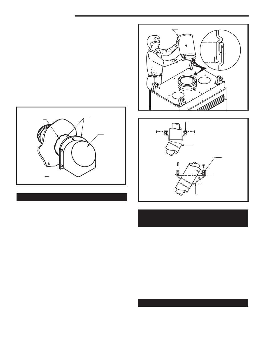
Installing the Chimney System
Start by attaching the first chimney section to the collar
on top of the fireplace.
Install the pipe as pictured in Figure 15. When you
get a good lock, you will hear the pipe clearly snap
together. Once sections are snap-locked in place, it is
extremely difficult to get them apart. Make sure the
pipe is firmly snapped and locked together as each
pipe section is mounted.
When installing elbows, only outer pipe will snap- lock.
Middle pipes simply slide into position. Be sure to
always attach straps on upper elbow to a structural
framing member. (Fig. 16)
Continue installing the pipe as required until pipe is
installed up through the ceiling. At this point, you must
install a firestop spacer.
FP270/271
CR Series
2/19/99 djt
Support Structure
Ceiling Hole
Framing
Elbow Strap
(must be tight)
Elbow Strap
Angled Strap
Angled Firestop
Chimney Support Strap
(must be tight)
FP270/271
Fig. 16 Attach straps to a structural framing member.
Installing the Firestop Spacer
in the Ceiling Hole
A firestop spacer is used to keep pipe spaced properly
and required for safety.
Nail the firestop spacer (at each corner) to the framing
members of the ceiling hole. NOTE: A firestop spacer
is not required at the roof.
Hole sizes listed in Figure 9 for angled firestop spacers
provide minimum required air space to chimney pipe for
ceiling thickness up to 8” (203mm). When combined
thickness of ceiling material, ceiling joists and flooring
material exceeds 8” (203mm), adjustments must be
made in framing to assure that minimum air spaces to
chimney are maintained.
Proper Firestop Spacer Installation
Figure 17 shows different installation procedures for
both an area that is an attic and an area that is not an
attic.
provided). Continue attaching the ducting together
using three (3) screws at each joint until you have
installed sufficient duct to arrive at your duct termina-
tion location.
3. At the termination end, install the duct termination.
This should be installed from the outside of the
home. Cut a hole in the desired location approxi-
mately 4¹⁄₂” in diameter, caulk around the hole, and
slide the termination through the opening from out-
side the home. The termination/rain cap should be
caulked around its perimeter to assure a tight seal.
The rain cap opening should be positioned down-
ward. (Fig. 14)
The AK-MST Outside Air Kit is now installed and ready
for use.
FP1061
AKMST
rain cap
7/6/00 djt
Caulking
Wall
Duct Termination
Rain Cap
FP1061
Fig. 14 Caulk and install duct termination/rain cap in place.
UP
FP1566
EWF Pipe install
Circulating models
3/05 djt
Pipe Section
Pipe
Rim
Hem
Lance
Pipe
Hem
FP1566
Fig. 15 Install pipe, listening for the snap-lock to fasten.