Fig 4, Fig 4b fig 4a flange up – PDR Mounts awm250 User Manual
Page 7
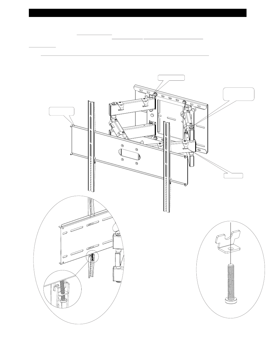
4. TYPICAL PDR PANEL MOUNTING TO ARTICULATING ARM, TENSION CONTROL
Lift the display with the wall arms attached on to the AWM250 and center the display on the mounting plate.
Assemble the locking tab (items 9 & 10) and insert into the slot in the display arm. (
See Fig 4a & 4b)
Center the display on the mounting plate and tighten the screws (
10) on the locking tab (9). Care should be taken not to over tighten screws (10).
Attach the cable brackets (
5) on the top and middle tube only using the self tapping screws (4) supplied. If the self tapping screws (4) are used for the cable brackets (5)
and the screw lock tab, remember to install the screw lock tab.
Failure to do so could allow the long shaft to loosen and fall out .Check cable position to make sure
cable is not pinched when the mount is opened or closed.
Adjusting tension: The tension bolt adjustments may be necessary to keep the display from creeping from the desired location. Loosen the screw (4) and lift the screw
lock tab and swing to the side. Using two 7/16 wrenches, tighten the tension bolts
until enough tension is applied to keep the display from creeping from the desired
location.
Make sure to replace the screw (4) and lock tab . Failure to replace could result in the tension bolt and shaft falling out. Tighten the tension bolts to suit
the weight of the display.
7
Fig 4
Cable Hanger
Fig 4b
Fig 4a
Flange up
Tension bolt &
screw lock tab
View from the back side of the AWM250
with locking tab in place
TENSION BOLT