Fig 2 fig 2a – PDR Mounts awm250 User Manual
Page 5
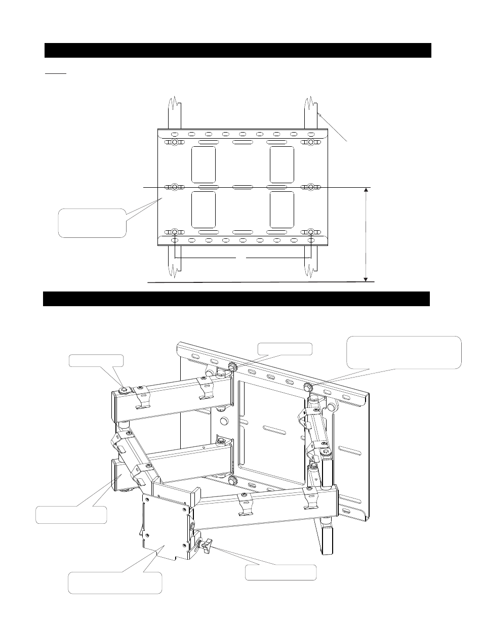
1. FASTEN MOUNTING PLATE TO WALL
Fig 2
Fig 2a
2. SECURE ARTICULATING ARM TO THE MOUNTING PLATE
Determine the exact mounting location for the wall mounting plate prior to the installation, considering the swing of the articulating arm.
CENTER of the wall studs capable of at least (4) times the weight of the display and
. The wall plate should be mounted at the same horizontal center line as
the desired display center line (viewing horizontal center line). Remove the (4) 3/8-16 hex head screws and washers holding the wall plate to the arm assembly (this will
make marking the holes easier). Position the wall mounting plate to the desired position. Mark and
Pre drill a 3/16” (5mm) hole for the lag bolts. Using the six lag bolts
and washers supplied (6 & 7), level and secure the mounting plate to the center of the wall studs. The wall mounting plate must be level left and right to prevent the
display from creeping from the wall.
Fig. 2
The plate must be secured to the
AWM250
After attaching the wall mounting plate to the wall, re-attach the articulating arm using the hardware previously removed. Using the different slots will aid in centering the
mount to the desired position left or right of center.
FIG 2a
5
Tilt adjust lever
Tension bolt
Tension bolt
FLOOR LINE
VIEWING
HORIZONTAL
CENTER LINE
WOOD STUDS
(std construction 2 x 4
studs and 1/2” wallboard)
Model # AWM250
16.00
WALL MOUNTING
PLATE
ARM ASSEMBLY
REMOVE 4 SCREWS
FOR MOUNTING WALL PLATE
MOUNTING PLATE REMOVED
FOR CLARITY