Nexen 5H20P-E 911317 User Manual
Page 9
6
FORM NO. L-20210-B-1209
PARTS REPLACEMENT
CLUTCH REMOVAL
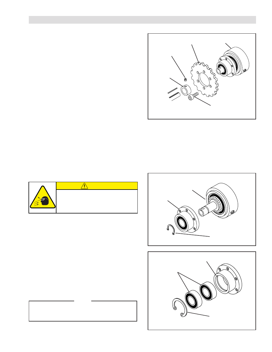
REFER TO FIGURE 2.
1. Shut off air supply to Clutch and remove Air Line
from Clutch.
2. Disengage Clutch from machine by removing chain
from sprocket.
3. Remove Set Screw (Item 16).
4. Slide Clutch and Hub Collar (Item 19) off shaft of
machine.
5. Remove Set Collar (Item 16).
6. Remove Socket Head Cap Screws securing
Sprocket to Clutch.
7. Remove Sprocket from Clutch.
FIGURE 2
Socket Head
Cap Screw
Sprocket
5H20P
Hub Collar
(Item 19)
Set Screw
(Item 16)
BEARING REPLACEMENT (DRIVE FLANGE)
REFER TO FIGURES 3 & 4.
Drive Flange
Cylinder/Piston
Assembly
FIGURE 3
FIGURE 4
Retaining Ring
(Item 11)
15
9
10
1. Remove Retaining Ring (Item 11).
2. Fully supporting Drive Flange; press Hub, and
Cylinder/Piston Assembly out of Drive Flange.
3. Remove Retaining Ring (Item 10).
4. Fully supporting Drive Flange (Item 15); press
Bearings (Item 9) out of Drive Flange.
5. Clean bore of Drive Flange with fresh safety solvent.
6. Apply Loctite
®
601 to O.D. of new Bearings, then
press new Bearings into Drive Flange.
NOTE
When installing new Bearings, carefully
align Bearing O.D. with Drive Flange Bore to
prevent Bearings misalignment.
7. Install Retaining Ring (Item 10).
CAUTION
Working with spring loaded or tension
loaded fasteners and devices can cause
injury. Wear safety glasses and take the
appropriate safety precautions.