Nexen Rod Locks 966195 User Manual
Page 7
7
FORM NO. L-21222-E-1211
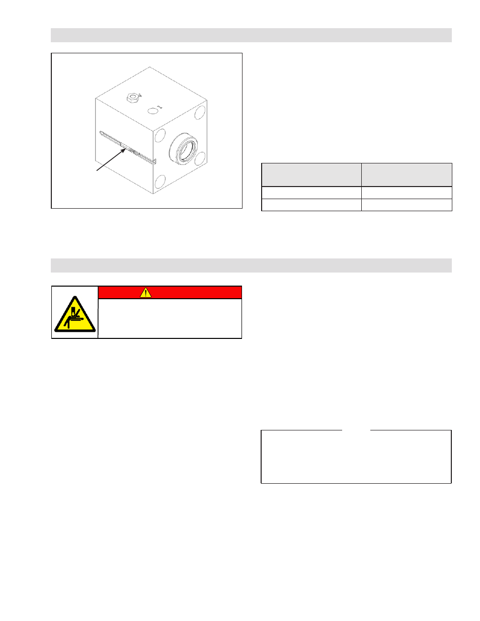
OPTIONAL LOCKING MODE SENSOR
AIR CONNECTIONS
1. The Nexen rod lock is equipped with a NPTF or BSPP
port for the air inlet. Route clean air, using soft or hard
lines, supplying at least 4.1 bar [60 psi] to facilitate full
disengagement.
NOTE: Install the valve in close proximity to the Rod
Lock unit for faster engagement and disengagement.
Higher air pressures will also speed the disengagement
time, but do not exceed 8.0 bar [120 psi] air pressure.
2. The Nexen rod lock is equipped with a port for the
internal vent (filters are included with most models).
If the air quality around the application is poor, route
the vent of the rod lock to a more suitable area, or
use a filtered breather. Contact Nexen for available
components.
NOTE: Clean air is important for proper Rod Lock
functioning. Debris inside the Rod Lock may inhibit
performance and/or shorten the life of the product.
DANGER
Support the load before disengaging
the Rod Lock. Failure to support the
load could result in serious bodily
injury.
All Nexen pneumatically actuated devices require clean
and dry air, which meet or exceeds ISO 8573.1:2001
Class 4.4.3 quality.
NOTE
For quick response, Nexen recommends a quick
exhaust valve and short air lines between the
Control Valves and the unit. Align the air inlet ports
to a down position to allow condensation to drain
out of the air chambers of the product.
Locking Mode
Sensor
Figure 2
Sensor Product
Number
Type
966190
NPN (Sinking)
966195
PNP (Sourcing)
Table 2 Inductive Sensor Product Numbers
Nexen “RLSSB” products are equipped with a T-slot
for an optional locking mode sensor (See Table 2). This
sensor can be positioned in the T-slot to relay when
the Rod Lock is disengaged or engaged on the shaft.
Once the sensor is properly located to relay when the
Rod Lock is in the desired state, use a standard flat-head
screwdriver or 1.5 mm allen wrench to turn the screw
and fix the sensor in the T-slot (See Figure 2).
- Rod Locks 966190 RLSSB 125-032-S-N 966074 RLSSB 100-025-S-N 966073 RLSSB 080-025-S-N 966072 RLSSB 063-020-S-N 966071 RLSSB 050-020-S-N 966070 RLSSB 040-016-S-N-MR 966028 RLSSB 040-016-S-N 966069 RLSSB 032-012-S-N 966068 RLSSB 125-032-S-A 966094 RLSSB 100-025-S-A 966093 RLSSB 080-025-S-A-MR 966025 RLSSB 080-025-S-A 966092 RLSSB 063-020-S-A 966091 RLSSB 050-020-S-A 966090 RLSSB 040-016-S-A 966089 RLSSB 032-012-S-A 966088 RLSSB 125-032-C-N-MR 966044 RLSSB 125-032-C-N 966034 RLSSB 080-025-C-N-MR 966042 RLSSB 080-025-C-N 966032 RLSSB 100-025-C-N-MR 966043 RLSSB 100-025-C-N 966033 RLSSB 063-020-C-N-MR 966041 RLSSB 063-020-C-N 966031 RLSSB 050-020-C-N-MR 966040 RLSSB 050-020-C-N 966030 RLSSB 040-016-C-N-MR 966039 RLSSB 040-016-C-N 966029 RLSSB 032-012-C-N-MR 966038 RLSSB 032-012-C-N 966036 RLSSB 125-032-C-A-MR 966024 RLSSB 125-032-C-A 966054 RLSSB 080-025-C-A-MR 966022 RLSSB 080-025-C-A 966052 RLSSB 100-025-C-A-MR 966023 RLSSB 100-025-C-A 966053 RLSSB 063-020-S-A-MR 966026 RLSSB 063-020-C-A-MR 966021 RLSSB 063-020-C-A 966051 RLSSB 050-020-C-A-MR 966020 RLSSB 050-020-C-A 966050 RLSSB 040-016-C-A-MR 966019 RLSSB 040-016-C-A 966049 RLSSB 032-012-C-A-MR 966046 RLSSB 032-012-C-A 966048 RLSSB 600-138-S-N 966176 RLSSB 500-138-S-N 966276 RLSSB 400-138-S-N 966262 RLSSB 325-100-S-N 966248 RLSSB 200-100-S-N 966234 RLSSB 500-100-S-N 966269 RLSSB 400-100-S-N 966255 RLSSB 400-100-S-N-MR 966149 RLSSB 250-063-S-N 966241 RLSSB 200-063-S-N 966227 RLSSB 600-175-S-A 966392 RLSSB 600-138-S-A 966284 RLSSB 500-138-S-A 966277 RLSSB 400-138-S-A 966263 RLSSB 325-100-S-A-MR 966137 RLSSB 325-100-S-A 966249 RLSSB 200-100-S-A 966235 RLSSB 500-100-S-A 966270 RLSSB 400-100-S-A 966256 RLSSB 400-100-S-A-MR 966148 RLSSB 250-063-S-A 966242 RLSSB 200-063-S-A 966228 RLSSB 150-063-S-A 966221 RLSSB 600-138-C-N-MR 966166 RLSSB 600-138-C-N 966362 RLSSB 500-138-C-N-MR 966165 RLSSB 500-138-C-N 966358 RLSSB 500-100-C-N 966356 RLSSB 400-138-C-N 966338 RLSSB 400-138-C-N-MR 966158 RLSSB 500-100-C-N-MR 966159 RLSSB 400-100-C-N-MR 966157 RLSSB 400-100-C-N 966336 RLSSB 325-100-C-N-MR 966139 RLSSB 325-100-C-N 966332 RLSSB 200-100-C-N-MR 966127 RLSSB 200-100-C-N 966308 RLSSB 150-063-S-N 966220 RLSSB 250-063-C-N-MR 966128 RLSSB 250-063-C-N 966326 RLSSB 200-063-C-N-MR 966126 RLSSB 200-063-C-N 966306 RLSSB 150-063-C-N-MR 966106 RLSSB 150-063-C-N 966303 RLSSB 600-175-C-A-MR 966385 RLSSB 600-138-C-A-MR 966162 RLSSB 600-138-C-A 966363 RLSSB 500-138-C-A-MR 966156 RLSSB 500-138-C-A 966359 RLSSB 400-138-C-A 966339 RLSSB 325-138-C-A-MR 966136 RLSSB 400-138-C-A-MR 966147 RLSSB 500-100-C-A-MR 966155 RLSSB 500-100-C-A 966357 RLSSB 400-100-C-A-MR 966144 RLSSB 400-100-C-A 966337 RLSSB 325-100-C-A-MR 966134 RLSSB 325-100-C-A 966333 RLSSB 250-100-C-A-MR 966124 RLSSB 200-100-C-A-MR 966117 RLSSB 200-100-C-A 966309 RLSSB 250-063-C-A-MR 966123 RLSSB 250-063-C-A 966327 RLSSB 200-063-C-A-MR 966116 RLSSB 200-063-C-A 966307 RLSSB 150-063-C-A-MR 966105 RLSSB 150-063-C-A 966304