Mounting on a rail – Nexen TCC-7 835168 User Manual
Page 7
7
FORM NO. L-21600-E-0411
NOTE: The Rail Brake Shoe gap is set at the factory
to accommodate standard rails. Shoe gap is not
adjustable.
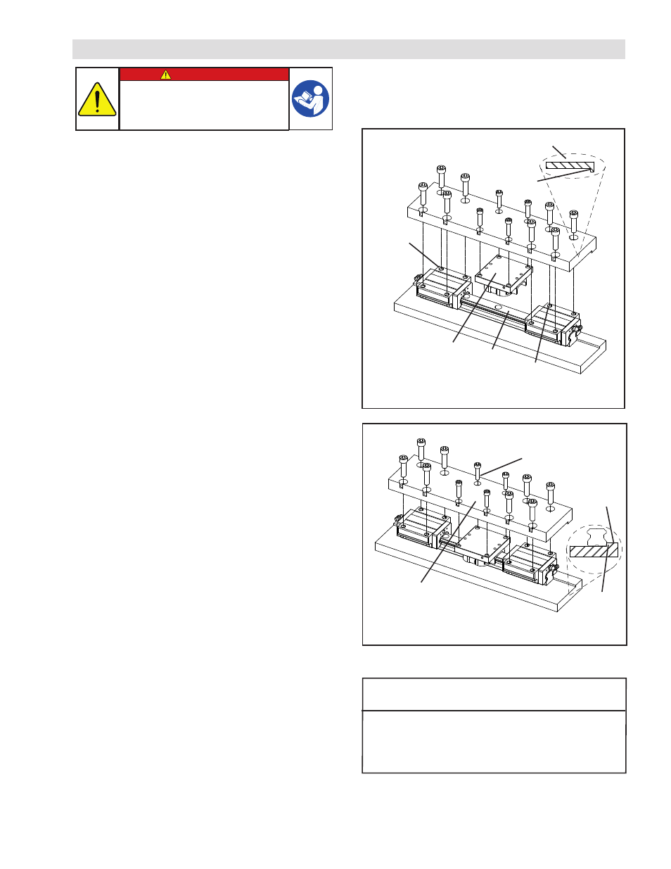
NOTE: Nexen rail brakes do not have an internal bearing
system and must be mounted in conjunction with at
least two bearing carriages (see figures 2 and 3). To
ensure proper alignment, the bearing carriages should
be mounted to a reference shoulder on the mounting
plate (see figures 2 and 3). Nexen rail brakes, however,
should not be aligned to the reference shoulder, but
must be allowed to self-center on the rail. Accurate
alignment is crucial to ensure proper brake function
and prevent facing drag. For successful alignment,
follow the installation steps below:
1. Nexen recommends a setup similar to the one shown
in Figures 2 and 3. Apply air pressure to the rail brake
to disengage it.
2. Slide the rail brake onto the rail. Position the rail brake
between two bearing carriages as shown.
3. Loosely assemble the mounting plate to the rail brake
and bearing carriages.
NOTE: RBR25; for THK SHS and INA KUVE models,
install the shim (shipped loose with these models)
between the mounting plate and the brake to match
bearing height.
4. Align the bearing carriages to the reference shoulder
and completely tighten the bearing carriage mounting
screws.
5. Finger-tighten the rail brake mounting screws. Do not
over-tighten the screws at this point; the brake must
be allowed to shift slightly in the following step.
6. Engage the rail brake to lock it onto the rail. Disengage
and reengage it three successive times to ensure that
it centers on the rail.
7. With the rail brake engaged, completely tighten the
rail brake mounting screws.
8. Disengage the rail brake and slide the assembly
back and forth to check alignment. If the rail brake
consistently drags along the rail, repeat steps 3-7
to realign the brake. If the rail brake drags only in
certain locations along the rail, check and adjust rail
straightness in those areas. If realignment and rail
straightening do not fix problems with facing drag,
the disengagement pressure of the rail brake can be
increased to 5.0 bar [72 psi] to ensure a minimum of
.05 mm [.002”] facing-to-rail clearance per side.
Table 1
Model
Socket Head Cap Screw
1
Size
RBR20
M6 x 1.0
RBR25
M6 x 1.0
RBR30
M6 x 1.0
RBR35
M10 x 1.5
1 Important: Do not use flat-head screws for this installation.
Figure 2
*Customer Supplied
Bearing*
(2x min.)
Bearing*
Rail Brake
Rail*
Datum Plane
Table (end view)
Figure 3
Bolts*
Mounting
Plate*
*Customer Supplied
Mounting
Shoulder
Datum
Plane
MOUNTING ON A RAIL
DANGER
Rail brake alignment is critical for proper
function. Carefully follow steps 1-8 to ensure
a successful rail brake installation. Improper
installation can damage your system and
cause serious injury or death.
NOTE: Rail Brake must be disengaged with a minimum
of 60 psi before mounting on a rail. Apply air pressure to
disengage the Rail Brake (Refer to AIR CONNECTIONS
for details).