Bradford White TGHE-199I-N User Manual
Page 38
38
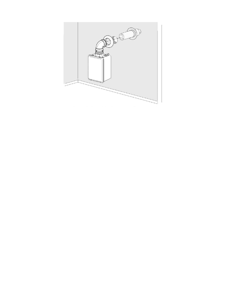
Final Installation of the Vent System
Figure 29.
Illustration Showing the Installation of a Horizontal Vent System.
From the outside of the building, slide the wall discharge terminal through the vent wall passage. A
supplied rubber wall plate can be installed on the exterior of the building. Slide the inner wall plate onto
the terminal. If necessary, apply silicon sealant to fill up spaces between vent terminal and the wall. Vent
connections must be firmly pressed together so that the gaskets form an airtight seal.
This manual is related to the following products:
See also other documents in the category Bradford White Water boiler:
- EFR-1-60T1206EN (76 pages)
- S-2-TW65T6FBN (11 pages)
- D-38T-155-3X (1 page)
- PDX1-40S6FSX (13 pages)
- EF-100T-300-3X (92 pages)
- M-4-30T6FBN (40 pages)
- M-4-30T6FBN (28 pages)
- M-4-30T6FBN (32 pages)
- M-4-30T6FBN (28 pages)
- M-2-XR75S6BN (1 page)
- M-I-30T6FBN (30 pages)
- PDX2-75T6FBN (44 pages)
- U1-50L6FRN (28 pages)
- U-1-75S6RN (1 page)
- U4-40T6FRN (12 pages)
- U1-50L6FRN (12 pages)
- M-2-TW-50T6FSX (36 pages)
- M-2-TW-50T6FSX (36 pages)
- M-4-XRTW50T6FSX (40 pages)
- TW4-50S-67FB-3X (40 pages)
- TW4-50S-67FB-3N (44 pages)
- M-2-TW-50T6FSX (44 pages)
- C-SW2-TW75T10BN (8 pages)
- GX-2-25S6SX (28 pages)
- C-SW2-75T10BN (28 pages)
- S-2-65T6FBN (28 pages)
- PE-4-403S6FBN (16 pages)
- PE-4-40T6FBN (68 pages)
- PE-4-403S6FBN (32 pages)
- GX-2-25S6SX (28 pages)
- M-I-100T6SX (28 pages)
- C-SW2-75T10BN (4 pages)
- C-SW2-75T10BN (25 pages)
- HE-4-40S6FBN (16 pages)
- HE-4-40S6FBN (40 pages)
- UDS1-50S6FRN (32 pages)
- DH-50T-50FB-3X (40 pages)
- DS1-40S6FBN (32 pages)
- U-1-75S6RN (28 pages)
- U-75T-80R-3N (8 pages)
- D-4-403S6FBN (40 pages)
- D-4-403S6FBN (36 pages)
- GX-2-TW-25S6SX (40 pages)
- U-1-TW-40S6FRN (48 pages)
- M-1-TW-40S6FBN (40 pages)