1 main power, 2 field wiring, Page 25 – Bradford White BMT2V0400 User Manual
Page 25
Brute Deluxe (200, 300, 400)
Page 25
STAGE 2
STAGE 1
CTL
BD
GAS
VALVE
GAS
VALVE
IGN CTL
VAL
FLOW
SW
PRSW
BURNER
IGN CTL
PSW
IGN CTL
TH
CNTRL
BD
FIELD
INTERLOCK
T
T
CNTRL
BD
2
4
CNTRL
BD
24V-
CNTRL
BD
PUMP
STATUS
SW
FUSIBLE LINK
MODEL 200
ONLY
MANUAL
RESET
HIGH LIMIT
VENT STK
PR SW
+24
IGN CTL
24V
BLOWER
IGN CTL
F2
IGN CTL
F1
MAIN PWR SW
120 VAC
HSI IGNITOR
IGN CTL
L2
IGN CTL
IGN/FS
IGN CTL
IGN/120
IGN CTL
L1
120 VAC
120 VAC
CLASS 2 50 VA
TRANSFORMER
PUMP
(IF EQUIPPED)
24 VAC
+24
1
W
CNTRL
BD
24V+
IGN CTL
GND
BK
R
BK
BLACK
BK
BROWN
BR
RED
R
ORANGE
O
YELLOW
Y
GREEN
G
BLUE
BL
VIOLET
V
GRAY
GY
SLATE
S
WHITE
W
WIRE
COLOR
DESIGNATION
-
+
+
-
1
INDUCER FAN
FIELD
WIRING
ON OFF
1 2 3 4
3.6
2.0
0.4
SWITCHED 120 VAC TO PUMP
120 VAC L
DHW CALL
COM CALL
HEAT CALL
OUT
COM
SYS
BOILER
SENSOR
4 3
2 1
POWER
HEAT CALL
DHW CALL
WWSD
CURVE
H2357600-
GY/V
BK
GY/BK
GY/BK
V/W
BR/BK
BR/BLK
G
W
BK
BK
BL/R
IGN/FS
E0253400
VAL
IGN
240
L1
PSW
GND
F1
F2
24
VAC
TH
FC -
IGN
120
L2
Y
BL/R
FIELD
INTERLOCK
BL/R
F1
BL/R
FUSE
BK
R/W
Y
G
TRANSFORMER
115 VAC INPUT
24 VAC OUTPUT
24V
115V
L1
BK
W
W
W
POWER
BK
BK
BK
BK
L2
W
PUMP
PUMP LOAD MUST NOT
EXCEED 5 AMPS.
G
G
BK
W
BK
BK
W
PUMP
STATUS
SWITCH
CONNECTOR
SHOWN FROM
REAR OF BOARD
BK
R
SENSOR
Y
Y
Y
R/BK
R
Y
R
Y
BL
R/BK
BR/BK
BR/R
Y
RELAY
FOR
2-STAGE
VENT STACK
PRESSURE
SWITCH
BL/W
BL/R
HIGH
TEMPERATURE
LIMIT
MANUAL RESET
MANUAL RESET
TEMPERATURE LIMIT
SWITCH
FOR SIZE 200 ONLY
ST.1
6V
ST.2
6V
Y/BLK
Y/BLK
BR/R
BR/BLK
STAGE 2
GAS VALVE
STAGE 1
GAS VALVE
PRESSURE
SWITCH
AIR
BOX/BURNER
FLOW
SWITCH
BLOWER
BL
R/BK
R/BK
BK
+
6
5
3
4
2
1
R
TB1
FIELD
FIELD
+24
-24
-24
+24
BL
R
BK
NO
C
NC
IGNITOR
V/W
V/W
R
NO
P
C
8
7
4
RELAY
6
3
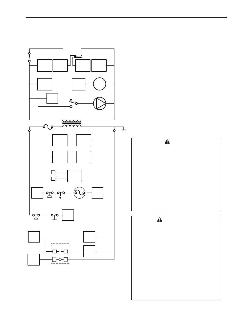
Figure 16. Logic Diagram, ON/OFF Boiler or Water Heater.
SECTION 5.
Electrical Connections
Single pole switches, including those of safety
controls and protective devices must not be wired in a
grounded line.
NOTE: All internal electrical components have been
pre-wired. No attempt should be made to connect
electrical wires to any other location except the
wiring box.
5.1 Main Power
Connect a 15 amp. fused, 120-volt supply to
the main power switch. Both hot and neutral wires
are provided for connections inside the boiler jacket.
Ground wire can be connected to the grounding screw
in the box.
Wiring diagrams are shown in
Figures 15 - 16
.
5.2 Field Wiring
Field Installed Pump: See
Figure 15
, Wiring
Diagram. Do not exceed 5 amps or control damage
could occur.
WARNING
The appliance must be electrically grounded
in accordance with the requirements of the
authority having jurisdiction or, in the absence
of such requirements, with the latest edition
of the National Electrical Code, ANSI/NFPA
70, in the U.S. and with latest edition of CSA
C22.1 Canadian Electrical Code, Part 1, in
Canada. Do not rely on the gas or water
piping to ground the metal parts of the boiler.
Plastic pipe or dielectric unions may isolate the
boiler electrically. Service and maintenance
personnel, who work on or around the boiler,
may be standing on wet floors and could be
electrocuted by an ungrounded boiler.
AVERTISSEMENT
L’appareil doit être relié à la terre
conformément aux exigences de la
réglementation locale ou, en l’absence d’une
telle réglementation, à la plus récente édition
du National Electrical Code (Code national de
l’électricité) ANSI/NFPA 70 aux États-Unis, et
à la plus récente édition du Code Canadien
de l’électricité 1
ère
partie (Canadian Electrical
Code Part 1) CSA C22.1, au Canada. N’utilisez
pas les tuyauteries d’eau ou de gaz pour
mettre à la terre les pièces métalliques de la
chaudière; des tuyauteries en plastique ou des
raccords union diélectriques peuvent isoler
électriquement la chaudière. Les employés
qui sont appelés à travailler sur la chaudière
ou autour peuvent être électrocutés par une
chaudière qui n’est pas mise à la terre.