Internet version for reference only – Bradford White M-I-MH40T6FLX User Manual
Page 9
Internet Version For Reference Only
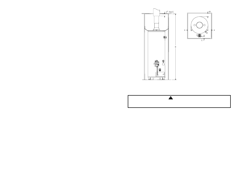
Minimum Clearances From
Combustible Materials
A
0” (0cm) Left, 2” (5.08cm)
Right (113.6 Liters Only)
B
0” (0cm)
C
4” (10.16cm)
D
78” (1.98m) m
VENT
----
Figure 1
Venting
WARNING
The vent system must be installed properly. Failure to properly install the
vent system could result` in property damage, personal injury, or death.
Make certain the flue baffle is in place and centered in flue tube. Place the
draft diverter over the flue opening at the top of the water heater by inserting
the tips of the draft diverter legs into the four (4) holes provided in the water
heater top. Cut a 7 1/4 inch (18.5cm) diameter hole in the ceiling and roof
directly above the flue of the water heater. Center the water heater beneath
the 7 1/4 inch (18.5cm) diameter holes in the roof and ceiling for proper
alignment of the draft diverter and roof jack vent. Apply non-hardening mastic
on the roof, around the previously cut hole, to form a weather seal with the
flashing of the gas vent roof jack assembly. Insert gas vent roof jack
assembly from above and fasten the flashing to the roof through the pre-
punched holes in the flashing. Note: Only the roof jacks listed in Figure 4
can be used on this water heater. Apply additional non-hardening mastic to
complete the weather seal. Slip the 3inch (7.62cm) vent connector extension
that is shipped telescoped, into the gas vent roof jack assembly down onto the
draft diverter that is secured to the top of the water heater and fasten with the
two (2) sheet metal screws provided.
9