Fig. 9, Fig. 10 – Allen&Heath W21442-SL1 User Manual
Page 8
ALLEN & HEATH
MIXWIZARD WZ14:4:2+ SYS-LINK OPTION
8
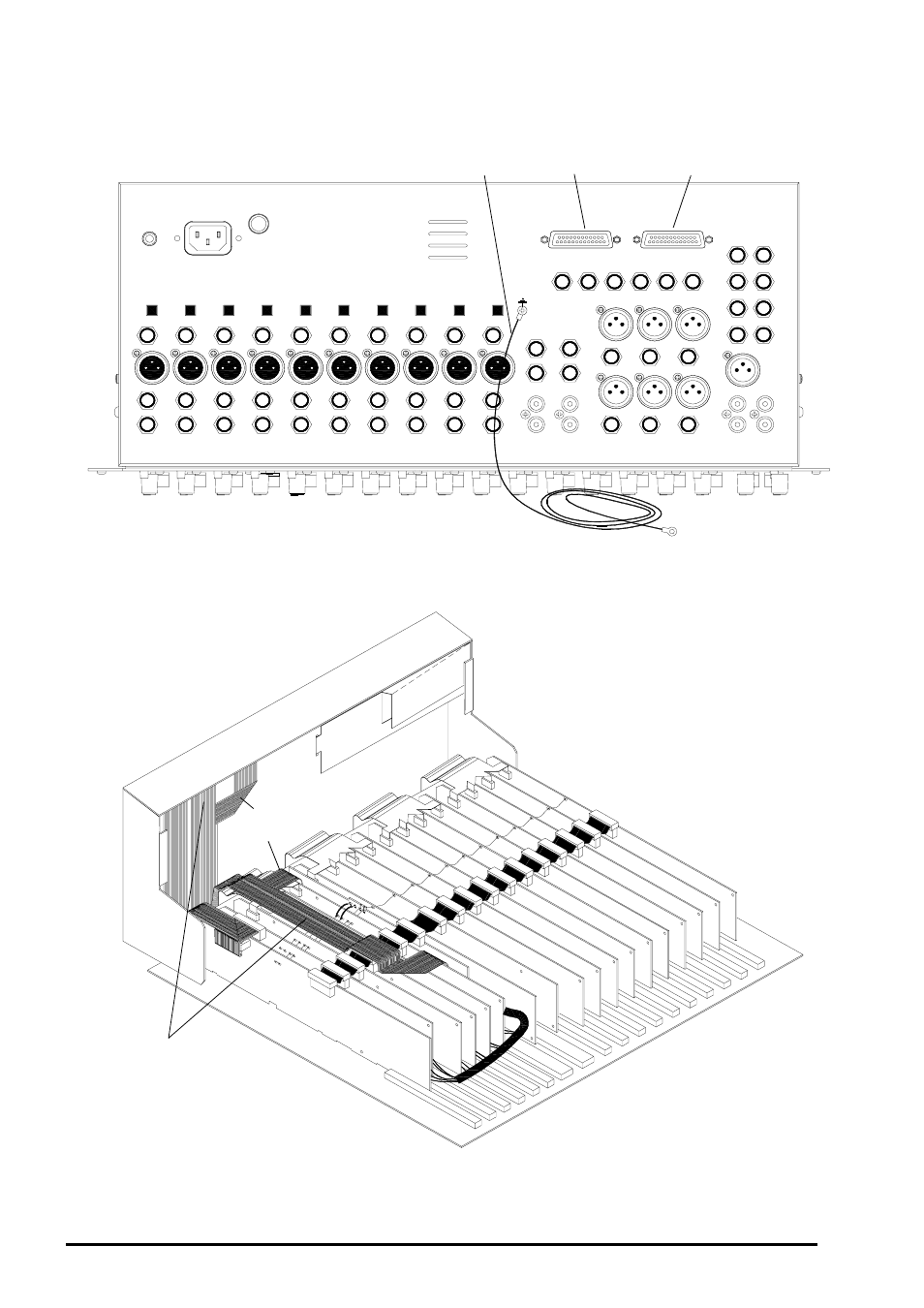
fig. 9
A
B
B B
B
B
B
A
A
Ribbon A
INPUT
INPUT
Ribbon A
Ribbon B
OUTPUT
INPUT
OUTPUT
OUTPUT
Ribbon B
Refering to fig. 10, place the 2 SYS-LINK ribbon harnesses so that they locate in the slots in the
base.
Carefully refit the connector circuit board assembly ensuring each XLR, Jack and Phono socket
is correctly located. Check all rear panel switches operate correctly.
fig. 10
Refering to fig. 1 & fig. 9, remove the two screws fixing the blanking panel in place and fit the two
SYS-LINK connectors. Check the connectors are fitted into the correct holes. Fit the 32/0.2
Green wire to the panel using the M3 x 12 screw provided as shown below.
1 Metre Green
32/0.2 wire
See also other documents in the category Allen&Heath Equipment:
- GL2800M (23 pages)
- XONE:DX User Guide (67 pages)
- XONE:3D (42 pages)
- XONE:32 (25 pages)
- XONE:1D Quick Start (2 pages)
- XONE:1D User Guide (14 pages)
- XONE:2D (34 pages)
- XB14 (40 pages)
- WZ20:8:2 Service Manual (35 pages)
- WZ16:2 (16 pages)
- WZ16:2DX (28 pages)
- WZ14:4:2 (24 pages)
- WZ1442-MK1 (21 pages)
- MIXWIZARD3 12:2 (30 pages)
- MIXWIZARD3 14:4:2 (27 pages)
- MIXWIZARD3 20S (32 pages)
- ML3000 (48 pages)
- ML3000 (48 pages)
- ML3000 Using LCRplus (2 pages)
- ML3000 VCA Groups (3 pages)
- ML4000 SIDECAR (4 pages)
- ML5000 SIDECAR (4 pages)
- ICON User Guide (67 pages)
- ICON Service Manual (25 pages)
- DR128-66 (44 pages)
- DR66 (28 pages)
- GL2000 User Guide v1 (16 pages)
- GL2200 User Guide v2 (28 pages)
- GL3000 v1 (16 pages)
- GL3300 v2 (20 pages)
- GL4 v1 (7 pages)
- GLD-80 User Guide (36 pages)
- GLD-80 Reference Guide (55 pages)
- GLD-AR8 (2 pages)
- MINI MULTI (3 pages)
- WAVES User Guide (19 pages)
- WAVES Quick Start (3 pages)
- WAVES Fitting Instructions (3 pages)
- M-MADI (4 pages)
- M-DANTE (4 pages)
- M-ACE (3 pages)
- iLive ACE (4 pages)
- AB168 (2 pages)
- GR2 (24 pages)