Allen&Heath W21442-SL1 User Manual
Page 6
ALLEN & HEATH
MIXWIZARD WZ14:4:2+ SYS-LINK OPTION
6
t
t
t
t
t
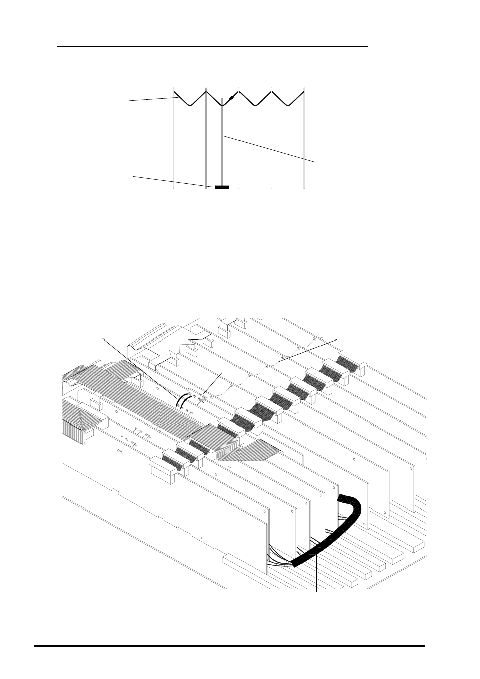
Bend the cut vertical TC buss wire back down and resolder.
Lift the SYS-LINK circuit board assembly and locate the Earth TC buss wire into the slot on the circuit board.
Make sure the SYS-LINK circuit board assembly is located centrally between the Stereo input circuit board
and the Group circuit board assemblies resting on the 2 foam strips.
Check that the TC buss wire is located in the correct slot and carefully solder it.
Solder red and black wires as shown in fig. 6.
SOLDERING THE SYS-LINK CIRCUIT BOARD ASSEMBLY:
Solder wires
onto TC buss
SYS-LINK
GROUP 1
STEREO 13-14
×
Slots
Buss wire
fig. 6
SYS-LINK
circuit board
Buss wire
Harness C
Foam Strip
See also other documents in the category Allen&Heath Equipment:
- GL2800M (23 pages)
- XONE:DX User Guide (67 pages)
- XONE:3D (42 pages)
- XONE:32 (25 pages)
- XONE:1D Quick Start (2 pages)
- XONE:1D User Guide (14 pages)
- XONE:2D (34 pages)
- XB14 (40 pages)
- WZ20:8:2 Service Manual (35 pages)
- WZ16:2 (16 pages)
- WZ16:2DX (28 pages)
- WZ14:4:2 (24 pages)
- WZ1442-MK1 (21 pages)
- MIXWIZARD3 12:2 (30 pages)
- MIXWIZARD3 14:4:2 (27 pages)
- MIXWIZARD3 20S (32 pages)
- ML3000 (48 pages)
- ML3000 (48 pages)
- ML3000 Using LCRplus (2 pages)
- ML3000 VCA Groups (3 pages)
- ML4000 SIDECAR (4 pages)
- ML5000 SIDECAR (4 pages)
- ICON User Guide (67 pages)
- ICON Service Manual (25 pages)
- DR128-66 (44 pages)
- DR66 (28 pages)
- GL2000 User Guide v1 (16 pages)
- GL2200 User Guide v2 (28 pages)
- GL3000 v1 (16 pages)
- GL3300 v2 (20 pages)
- GL4 v1 (7 pages)
- GLD-80 User Guide (36 pages)
- GLD-80 Reference Guide (55 pages)
- GLD-AR8 (2 pages)
- MINI MULTI (3 pages)
- WAVES User Guide (19 pages)
- WAVES Quick Start (3 pages)
- WAVES Fitting Instructions (3 pages)
- M-MADI (4 pages)
- M-DANTE (4 pages)
- M-ACE (3 pages)
- iLive ACE (4 pages)
- AB168 (2 pages)
- GR2 (24 pages)