Allen&Heath W21442-SL1 User Manual
Page 4
ALLEN & HEATH
MIXWIZARD WZ14:4:2+ SYS-LINK OPTION
4
Buss wire
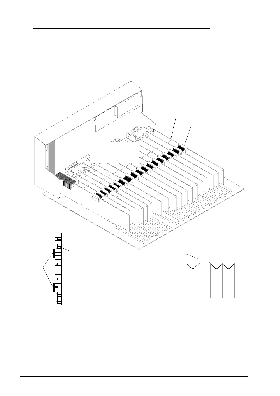
Locate Stereo input 13-14 circuit board assembly and Group 1 circuit board assembly. Referring
to fig.4 fit 2 x foam strips in between Stereo input 13-14 and Group 1 circuit boards. Remove the
IDC harness from the Right PCB all the way to Stereo input 13-14 PCB. Cut the TC buss wire
5mm from the component side of the Stereo input 13-14 circuit board assembly and bend the TC
buss wire vertically.
Slide the SYS-LINK circuit board in between the Stereo input channel and Group 1 circuit board
assemblies. Take care not to damage the ribbon harnesses already connected to the circuit
board.
Cut each wire 5mm from the component side of
stereo input 13-14 circuit board assembly and
bend wires vertically up.
Buss wire across channels
LEFT
RIGHT
MONO
GROUP 1
STEREO 13-14
Referring to fig. 1, fig. 5 & fig.6, form harness C as shown and prepare the solder pads on the
circuit boards with new solder to ease the soldering of the SYS-LINK wires.
Note, the wires are soldered to the trackside of the circuit boards and not the component
side.
It is recommended that the wires in the SYS-LINK harness are soldered to each circuit board in
the following order:
RIGHT PCB then LEFT then GROUP 4 then GROUP 3 then GROUP 2 and then finally GROUP
1 PCB.
SOLDERING THE SYS-LINK HARNESS ASSEMBLY:
q
q
q
q
q
r
r
r
r
r
fig. 4
Ø
SYS-LINK
circuit board
Р
Р
FITTING THE SYS-LINK CIRCUIT BOARD ASSEMBLY
Slide SYS-LINK circuit
board between Stereo
input 13-14 & Group 1.
IDC harness
STEREO 13-14
PCB
Potentiometers
Switches
GROUP 1
PCB
2x Foam
Strips
Group 1
Stereo 13-14