Typical installation – Vinten Radamec HS-105P Pan & Tilt Head User Manual
Page 19
HS-105P pan and tilt head
18
Typical installation
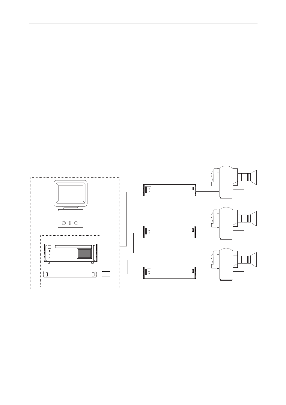
The head is typically installed as part of a robotic system and can be remotely controlled by the
Vinten Radamec Control System (VRC), Legislative Control System (LCS) or the Multi Controller
II. Refer to the appropriate user guide or operating instructions provided with the control system
for information on operating the head remotely.
Each head is connected to a 2U rack mounted power supply unit (AM-PSD27-5R) that supplies
the required DC voltage to the head by way of a combined power and data communications
floor cable over a maximum distance of 150m (500 ft). The controller connects directly to the
rack mounted power supply unit (AM-PSD27-5R) that can be sited a maximum distance of
1500m (5000 ft) from the head. All data cables must be screened and it is preferred that all
cabling is supplied by Vinten Radamec to minimise any problems caused by electrical
interference.
Any auxiliary equipment and lens drives can be connected directly to the HS-105 pan/tilt head.
A typical application is shown in Fig. 7.
Fig 7 Typical installation of the HS-105 pan/tilt head
AM-PSD27-5R
Touchscreen
monitor
Joystick Panel
System Unit
Video Switcher
Rack Mounted equipment
Controller
CAM 1
AM-PSD27-5R
AM-PSD27-5R
CAM 2
CAM 3
video
inputs
}
}
HS-105 head
HS-105 head
HS-105 head
CAM1
CAM2
CAM3