Components and connections, Ci box front view ci box rear and underside view – Vinten Radamec Ci Box ICE Interface User Manual
Page 6
4
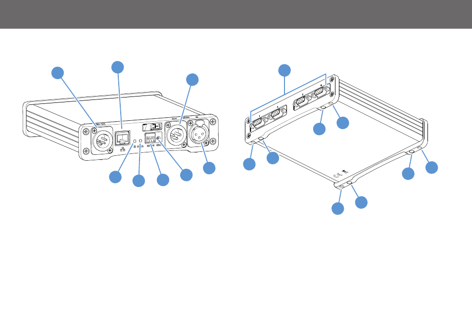
Components and Connections
Ci Box Front View
1 . . . . . . . . . . . . . . . . . . . . . . . . . . . . . . . . . . . . . . . . .Power connector
2 . . . . . . . . . . . . . . . . . . . . . . . . . . . . . . . . . . . . . . . Ethernet connector
3 . . . . . . . . . . . . . . . . . . . . . . . . . . . . . . . . . . . . . . Modem output port*
4 . . . . . . . . . . . . . . . . . . . . . . . . . . . . . . . . . . . . . . . Modem input port*
5 . . . . . . . . . . . . . . . . . . . . . . . . . . . . . . . . . . . . . .Modem gain control*
6 . . . . . . . . . . . . . . . . . . . . . . . . . . . . . . .Baud rate selection switches*
7 . . . . . . . . . . . . . . . . . . . . . . . . . . . . . . . . . . . . . . . Data indicator LED
8 . . . . . . . . . . . . . . . . . . . . . . . . . . . . . . . . . . . . . . Power indicator LED
Ci Box Rear and Underside View
9 . . . . . . . . . . . . . . . . . . . . . . . . . . . . . . . . . . . . . .Serial Connectors x4
10 . . . . . . . . . . . . . . . . . . . . . . . . . . . . . . . . . . . . . . . . . Mounting holes
11 . . . . . . . . . . . . . . . . . . . . . . . . . . . . . . .Rubber feet mounting points
* Ci-1 box only.
4
5
6
7
8
1
2
3
9
11
10
10
11
11
10
10
11