Preparing the condensing unit (continued) – Vintage Cellars Platinum Split Tech Manual User Manual
Page 30
Page 28 | 1-800-343-9463
PS
033114
PREPARING THE CONDENSING UNIT (continued)
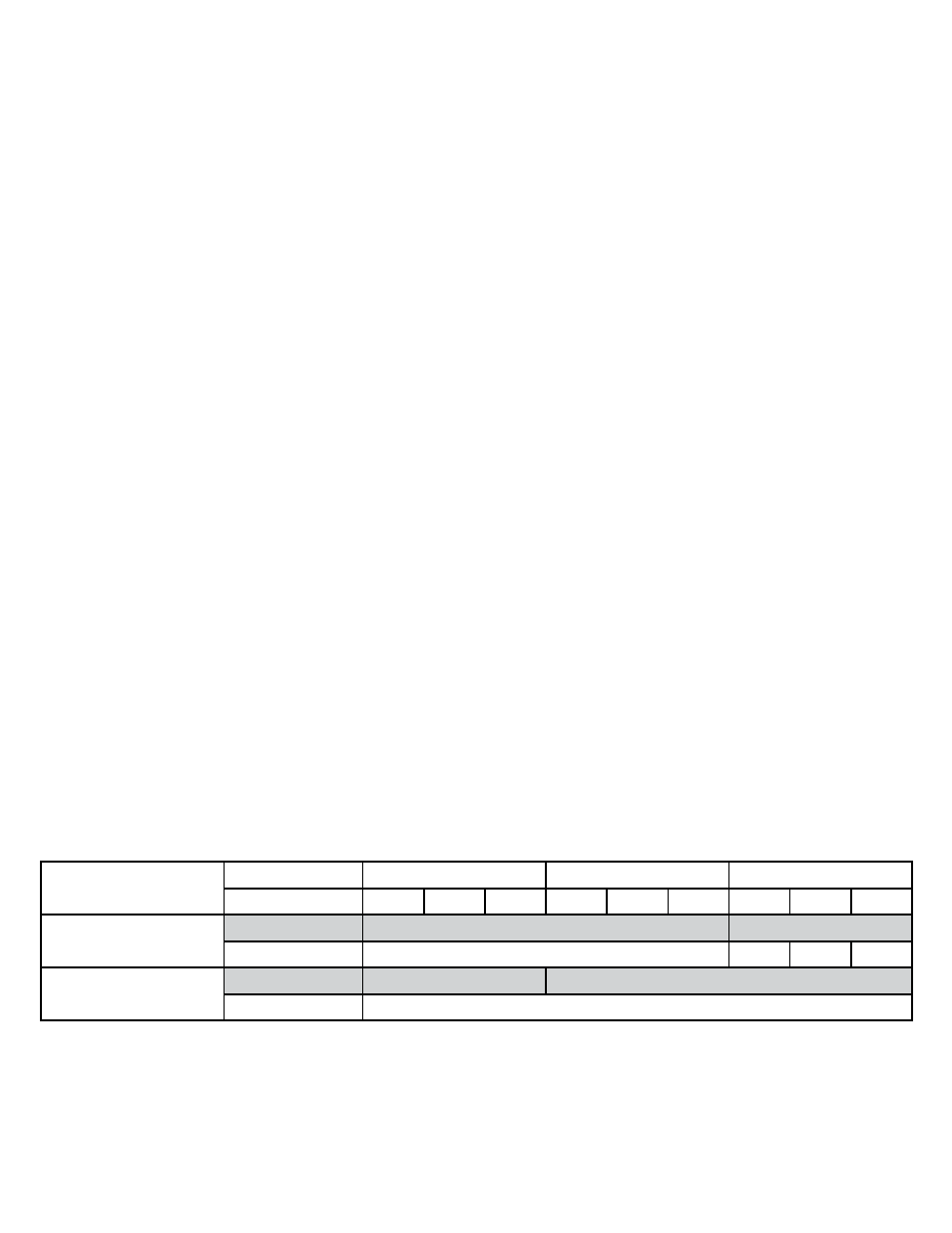
It is required to size the suction line tubing according to this chart.
Installing the Condensing Unit
The condensing unit can be installed inside a well ventilated area of the home, but it is typically installed outside.
Exterior applications will require the use of a protective housing, and the amount of sun exposure should be
considered when selecting the placement of the condensing unit .The condensing unit requires a dedicated 20 amp
circuit, non-GFI. Make sure there is a minimum three-foot horizontal clearance in front and rear of the unit. The unit
may either be hard wired or plug-in depending on local electrical codes.
Set the condensing unit level and with proper clearances in accordance with the instructions, name plate power
supplied, proper electric disconnect and fuse protection connected but not turned on and ready for piping
connections.
Inside Condensing Unit Installations: Inside installations require special consideration, as there must be
adequate ventilation to remove the heat created during normal operations. An exhaust port with fan may
need to be installed to ensure that heat is effectively removed from the utility room. A return grille or provision
for 500 - 600 cfm of cool air to enter the room to replace the exhausted air will accomplish this. Unobstructed
airflow to and from the unit is a critical factor in the unit’s overall performance. Make sure there is a minimum
three-foot horizontal clearance in front and rear of the condensing unit and at least one foot on each side. This
will assure that the unit can move the air around the room in an efficient manner.
Outdoor Condensing Unit Installations. You must utilize the exterior condensing unit housing for outdoor
installations. Place the condensing unit on a solid foundation in a location with adequate ventilation. There
should be three feet of clearance in the front and rear of the unit and one foot on each side. The unit should
be elevated 18 inches in order to avoid any possible flooding or damage by animals, and should be clear of
leaves, dirt, and other debris.
Head Pressure Control, Fan Cycling Switch:
These switches are used to cycle the condenser fan at low ambient temperature conditions. If your unit is equipped
with a Low Ambient Control, set the switch to 170 psig for cut-in and 70 psig for the differential. Further adjustment
may be needed. Verify the settings via refrigeration gauge and perform the final adjustments to the readings on the
gauge manifold set. If your condensing unit is not equipped with an adjustible Low Ambient Control, it features a pre-
set Fan Cycling Switch. These controls serve the same purpose, but have different names.
Refrigeration Lines
A 1/4 inch O/D copper “liquid line” is required
The refrigerant drier and the sight glass shall be installed (in that order) in the direction of the refrigerant flow in the
liquid line between the condensing unit and Evaporator Unit (Fan Coil Unit). Enclose the suction line in a cellular
insulation ½” wall thickness Armaflex (brand name) or equal to reduce heat transfer.
Model
Line Set Length
<25ft
26-50ft
50-100ft
Vertical Rice
<3ft 3-10ft >10ft
<3ft 3-10ft >10ft
<3ft 3-10ft >10ft
Platinum Split 4000
Horizontal Tubing
1/2”
5/8”
Vertical Rise
3/8”
5/8”
5/8”
1/2”
Platinum Split 8000
Horizontal Tubing
1/2”
5/8”
Vertical Rise
1/2”