Caution, Warning, Overlay door panel installation – Vintage Cellars ML24WD User Manual
Page 14
14
!
CAUTION
!
WARNING
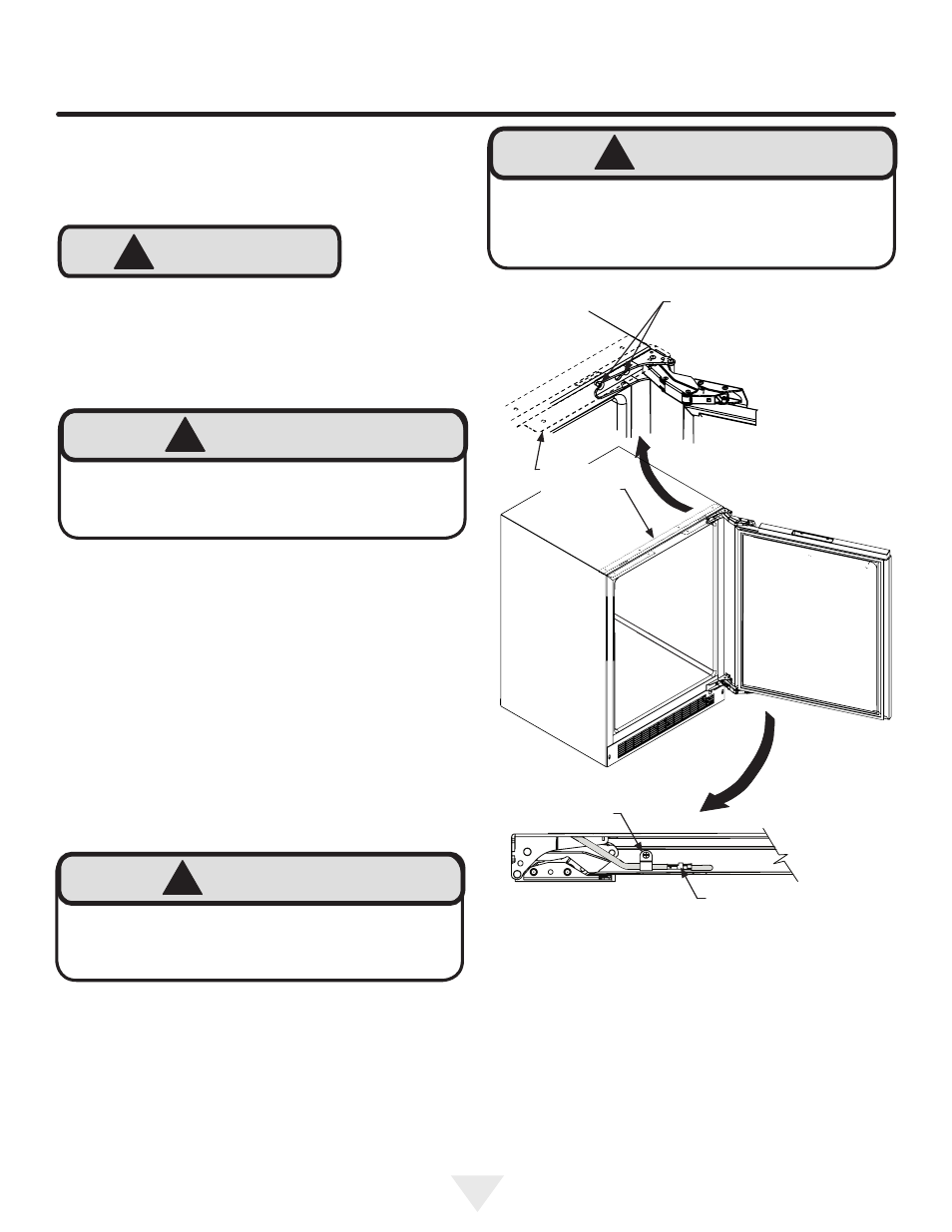
Cabinet
"Z" Bracket
!
WARNING
Use extreme caution with the articulated hinges. The
hinge is self closing and many pinch points exist prior
to built-in installation.
Do not remove the cabinet "Z"
bracket from the top of the cabinet.
!
WARNING
The articulated hinges have many pinch points. Care-
fully close / collapse the hinges as soon as the door is
removed from the cabinet.
Loosen (do not remove ) these
2 phillips head screws on the
top and bottom hinges
Figure 10a
Figure 10
"P" clamp
and screw
Wire connector
see Figure 11
Figure 10b
Bottom of
door
OVERLAY DOOR PANEL INSTALLATION
If you purchased an overlay panel model, your unit is
equipped with articulated hinges to allow fully integrated
built-in installations. Custom panel thicknesses of
5
⁄
8
" (15
mm) and
3
⁄
4
" (18 mm) are accommodated.
It is important to use the factory provided grille that came
with the product to assure proper air flow is maintained
through the condenser. The use of a custom grille is not
recommended and will void the warranty.
Overlay panel models are designed for use with
built-
in installations only. Use in freestanding installations
could result in personal injury.
Step 1: Removing the Door
With a phillips screwdriver remove the screw and "P" clamp
from the bottom of the door near the hinge. See Figure 10b.
Disconnect the door wire harness by pressing and holding
down the locking tab on the wire connector and pulling the
connector apart. See Figure 11.
Open the door and loosen the screws holding the hinges to
the cabinet (2 at the top and 2 at the bottom hinge). Do not
remove the screws but loosen them enough so the hinges
can be slipped off of the screws when sliding the door to
the side.
With a helper, and being careful not to scratch the cabinet
or the door, slide the door to the side about
1
⁄
2
inch and
remove the hinges and door from the unit.
Step 2: Remove the door gasket
With the door laying on a flat surface and starting at a
corner of the door remove the magnetic door gasket from
the interior side of the door, see Figure 12. Set the gasket
aside on a flat surface.
There are 10 holes in the gasket retainer extrusions, (3 on
each side and 2 at the top and bottom which are used to
fasten the panel to the front of the door. The screws are
provided in the literature pack.