Controller wire terminal output wiring – Tycon Power RPST2424-100-280 User Manual
Page 6
6
Note: The green connector
on the controller may be-
come unplugged due to vi-
bration and the weight of the
cables. Be sure to add a zip
tie or other method to hold
the cables and relieve the
cable weight from the con-
nector.
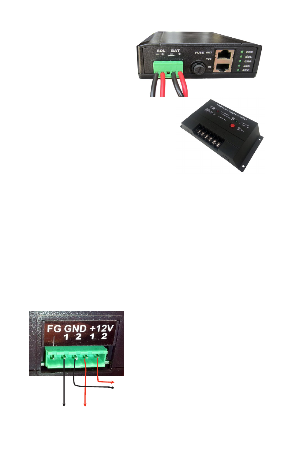
An alternate high capacity (20A) controller is
shipped with the RPST12 systems with
280W solar panels and is also available on
the RPST24 systems. The controller has
wire terminal solar, battery and unregulated
load outputs.
STEP 12: Route the solar panel cables out thru the feedthrus and
install to the solar panel. Be sure to connect in the proper polarity, red
wire to + and black wire to –. Make sure connections are waterproofed.
STEP 13: Tighten all wire feedthrus. If they don’t tighten on a small
diameter wire, you can wrap some electrical tape around the wire in the
seal area to increase its diameter and make a better seal. The enclo-
sure needs some small amount of venting so be sure not to seal all
holes and feedthrus with silicon.
STEP 14: Make sure lid gasket is clean and free from any parti-
cles, then carefully close the cover, making sure that wires are clear of
the seam and hinge area. Use the special key to close the two cover
locks.
Controller Wire Terminal Output Wiring
Device 1
Device 2
FG = Frame Ground (Do Not Connect
to V-)
GND = V- (There are two V– connec-
tions:1 and 2)
+12V or +24V = V+ (There are two V+
connections: 1 and 2)
+
-