E.3 wire, F. installation, F.2 step-by-step instructions – Tycon Power TPW-400DT 12/24V 400W Turbine User Manual
Page 3: F.2.1 connect the wires and mount the turbine
Page 3
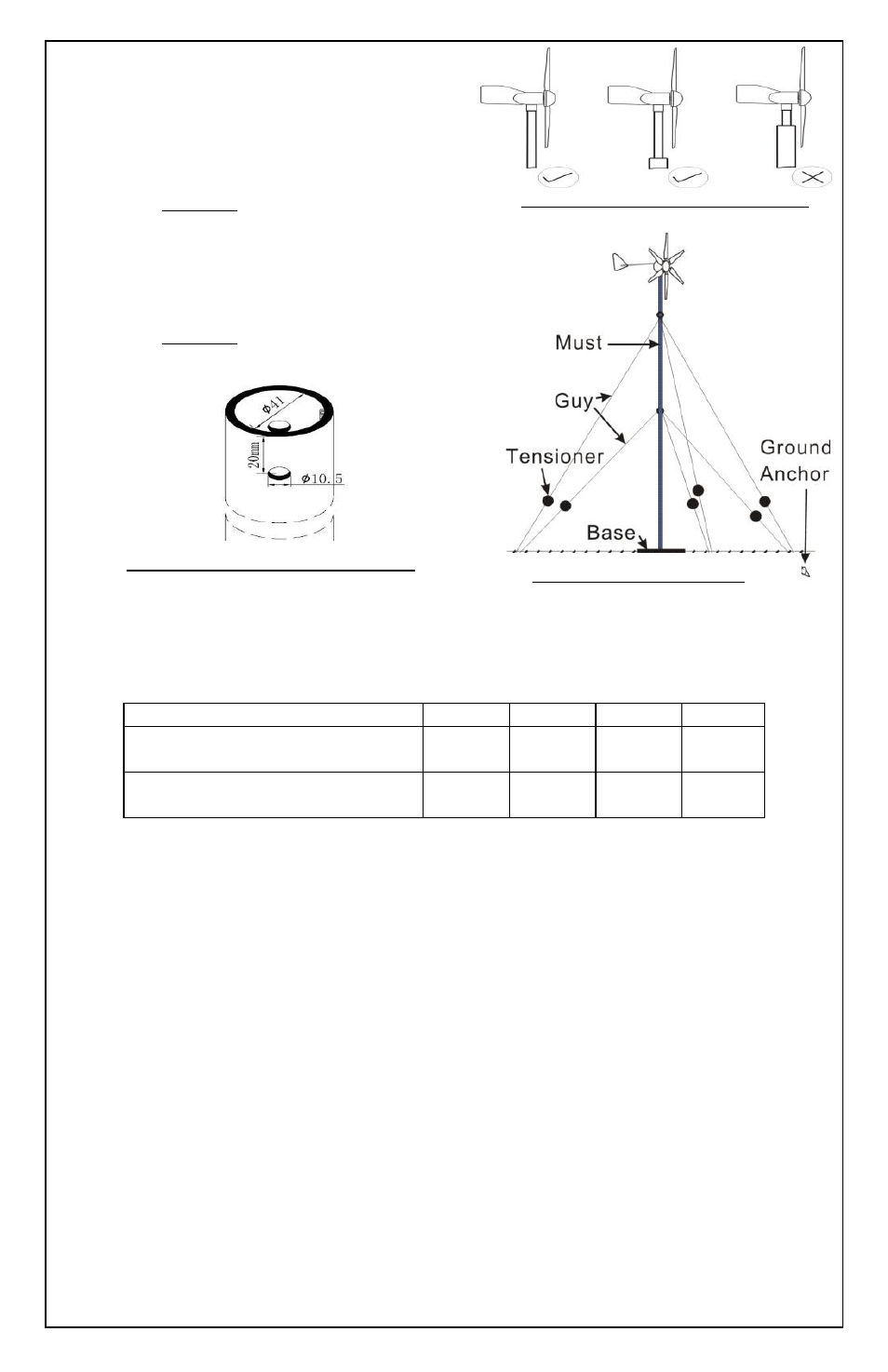
3. Make sure a minimum 50 cm
clearance is provided
between the blade tips and
any obstructions. Refer to
Figure 2.
4. Mark and centre-punch two
positions diametrically opposite,
at 90
°
to the pipe seam, 20mm
from top of the tube (Refer to
Figure 3). Then drill two 10.5mm
diameter holes.
E.3 Wire
If the cross section area of the wires is NOT sufficient, the wires will heat
up and could create a fire hazard. Please choose the right size of wire.
Minimum Wire Size (X-Section Area):
Distance From Batteries to Turbine 0-9M
9-18M
18-27M
27-45M
Wire X-Section Area for
12V Wind Turbine
4mm
2
12AWG
6mm
2
10AWG
8 mm
2
9AWG
10mm
2
8AWG
Wire X-Section Area for
24V Wind Turbine
2.5mm
2
14AWG
4mm
2
12AWG
6mm
2
10AWG
8mm
2
8AWG
F. Installation
F.1 Please follow these precautions during the installation:
1. THINK SAFETY! Have someone available to help when installing.
2. Disconnect batteries from turbine.
3.
Be careful not to pinch the wires when attaching the turbine to
pole.
F.2 Step-By-Step Instructions
F.2.1 Connect the wires and mount the turbine
1. Run the 2 wires from the battery location, through the pole to the
top of the pole. DO NOT connect the wires to the battery until
everything else has been completed. Strip the insulation back
from each side of wires. Mark both ends of the wires with tape to
identify the polarity: Red = Positive (+); Blue = Negative (-)
Figure 2: Blade and pole clearance
Figure 4: Typical Mounting
Figure 3: Mounting Pole Preparation