Tycon Power UPS-DC1212-9 User Manual
Page 3
3
STEP 7:
Mount any electronics boards to the metal plate. Install a
CAT5 cable between the controller POE OUT and the electronics.
There is a secondary voltage
output on the back of the control-
ler which can be used in addition
to the POE OUT. The secondary
output is equal to the battery
voltage.
On the bottom of the enclosure
there are double D cutouts for
standard N Female bulkhead
connectors which can be used
for an external antenna or RF
device. Just remove the hole
plug to use these cutouts.
STEP 8: Tighten the RJ45 Feedthru on the Cat5 cable. If the cable di-
ameter is too small to make a good seal, wrap a couple turns of electri-
cal tape around the CAT5 cable at the seal area to increase it’s diame-
ter.
STEP 9: Make sure lid gasket is clean and free from any particles, then
carefully close the cover, making sure that wires are clear of the seam
and hinge area.
STEP 10: Tighten the 4 seal screws evenly to seal the cover. Use a
grease or oil on the 4 cover attached screws to make it easier to re-
move later.
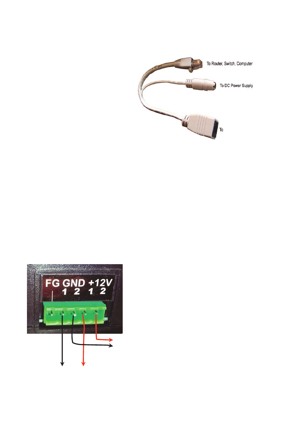
POE-IN of
controller
Device 1
Device 2
FG = Frame Ground (Do Not Connect to
V-)
GND = V- (There are two V– connec-
tions:1 and 2)
+12V or +24V = V+ (There are two V+
connections: 1 and 2)
+
-